Table of Contents
Advertisement
Quick Links
U1211A
The following items are included with your clamp meter:
✔
Standard test leads with 19 mm probes
✔
Soft carrying case
✔
Quick Start Guide
✔
Certificate of Calibration
If any item is missing or damaged, contact your nearest Agilent Sales
Office.
For more detailed information, please refer to the Agilent U1211A, U1212A,
and U1213A Clamp Meter User's and Service Guide on Agilent Website:
www.agilent.com/find/handheld-tools
Agilent U1211A, U1212A,
and U1213A Clamp Meter
Quick Start Guide
U1212A
Agilent Technologies
U1213A
and 4 mm probes
Advertisement
Table of Contents

Related Manuals for Agilent Technologies U1211A


Summary of Contents for Agilent Technologies U1211A
- Page 1 Certificate of Calibration If any item is missing or damaged, contact your nearest Agilent Sales Office. For more detailed information, please refer to the Agilent U1211A, U1212A, and U1213A Clamp Meter User’s and Service Guide on Agilent Website: www.agilent.com/find/handheld-tools Agilent Technologies...
-
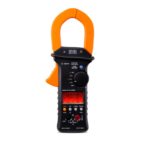
Page 2: Knowing Your Clamp Meter
Knowing Your Clamp Meter markings Clamp jaw Hand guard Hold/ Max Min button Handle Rotary switch Front panel Annunciator Function buttons Black input Red input terminal terminal Quick Start Guide... -
Page 3: Functions And Features
Functions and Features Rotary switch Measurements and power off functions Function buttons Actions Steps Freeze measured value Press Hold/Max Min • Record maximum, minimum, and • Press Hold/Max Min > 1 second calculate true average • Toggle between maximum, average, and •... -
Page 4: Annunciator Display
Annunciator Display Annunciator Status AUTO Indicates auto ranging Zeroing mode Data hold MAX AVG MIN Dynamic recording mode on present reading. MAX: maximum reading, MIN: minimum reading, AVG: average reading Direct current or voltage Alternating current or voltage Capacitor measurement unit Audible continuity indicator Current measurement unit Low battery indicator when battery voltage drops below 6.0 V... -
Page 5: Input Terminals
Input Terminals Ensure the terminal connections are correct for a particular WA RN ING measurement before making any measurement. To avoid damage to the device, do not exceed the input limit. Measurement Input terminals Input limits functions AC current Clamp jaw 1000 A DC current AC voltage... -
Page 6: Performing Current Measurement
Performing Current Measurement Ensure the test leads are disconnected from the input WA RN ING terminals when measuring current with the clamp meter. 1 Set the rotary switch to ~A. 2 Press Shift to switch between AC current, DC current (for U1212A and U1213A only), and AC+DC current (for U1213A only) measurements. - Page 7 Ensure that the clamp meter measures only one conductor CAU TI O N CAU TI O N at a time. Measuring multiple conductors may cause inaccuracy in measurement reading due to vector sum of currents flowing in the conductors. Current Current flow flow...
-
Page 8: Performing Voltage Measurement
Performing Voltage Measurement 1 Set the rotary switch to ~V. 2 Connect the red and black test leads to input terminals V (red) and COM (black) respectively. 3 Press Shift to switch between AC voltage, DC voltage, and AC+DC voltage (for U1213A only) measurements. 4 Probe the test points and read the display. -
Page 9: Performing Resistance Measurement And Continuity Test
Performing Resistance Measurement and Continuity Test 1 Set the rotary switch to Ω. 2 Connect the red and black test leads to input terminals Ω (red) and COM (black) respectively. 3 Probe the test points (by shunting the resistor) and read the display. 4 To perform continuity test, press Shift once. -
Page 10: Performing Diode Measurement
Performing Diode Measurement 1 Set the rotary switch to 2 Connect the red and black test leads to input terminals (red) and COM (black) respectively. 3 Probe the test points and read the display. Probe and read Connect Quick Start Guide... -
Page 11: Performing Capacitance Measurement
Performing Capacitance Measurement 1 Set the rotary switch to 2 Press Shift to select capacitance measurement. 3 Connect the red and black test leads to input terminals (red) and COM (black) respectively. 4 Probe the test points and read the display. Probe Press and read... -
Page 12: Performing Temperature Measurement
Performing Temperature Measurement For U1212A and U1213A only 1 Set the rotary switch to Ω. 2 Press Shift twice to select temperature measurement. 3 Connect the thermocouple adapter (with the thermocouple probe connected to it) into input terminals (red) and COM (black). 4 Touch the measurement surface (device under test) with the thermocouple probe and read the display. -
Page 13: Replacing The Battery
Replacing the Battery 1 Set the rotary switch to OFF. 2 Disconnect test leads from the input terminal. 3 Loosen the screw on the battery cover. 4 Lift the battery cover slightly, then pull the battery cover upwards. 5 Replace the specified battery (9 V). 6 Reverse the procedures above to close the cover. -
Page 14: Regulatory Markings
Regulatory Markings The CE mark is a registered trademark of the European Community. This CE mark shows that the product complies with all the relevant European Legal Directives. The CSA mark is a registered trademark of the Canadian Standards Association. ICES/NMB-001 indicates that this ISM device ICES/ complies with the Canadian ICES-001. - Page 15 CAT IV Category IV 600 V overvolt- age protection 600 V For further information on safety, refer to the U1211A, U1212A, and U1213A Clamp Meter User’s and Service Guide. Printed in Malaysia First edition, December 15, 2009 © Agilent Technologies, Inc., 2009...