
Related Manuals for Agilent Technologies U1731B


Summary of Contents for Agilent Technologies U1731B
- Page 1 Agilent U1731B/U1732B Dual Display Handheld LCR Meter User’s and Service Guide Agilent Technologies...
- Page 2 Notices Warranty Safety Notices © Agilent Technologies, Inc. 2009 – 2012 No part of this manual may be reproduced in The material contained in this docu- any form or by any means (including elec- ment is provided “as is,” and is sub-...
- Page 3 Caution: risk of danger (refer to this manual for specific Warning or Caution information. Protective conductor terminal Caution: hot surface. Frame or chassis terminal Out position of a bi-stable push control. Equipotentiality In position of a bi-stable push control. U1731B/U1732B User’s and Service Guide...
- Page 4 “Monitoring and Control Instrument” product. The affixed product label is shown as below: Do not dispose in domestic household waste To return this unwanted instrument, contact your nearest Agilent office, or visit: www.agilent.com/environment/product for more information. U1731B/U1732B User’s and Service Guide...
- Page 5 Failure to comply with these precautions or with specific warnings elsewhere in this manual violates safety standards for design, manufacture, and intended use of the instrument. Agilent Technologies assumes no liability for the customer’s failure to comply with these requirements. •...
- Page 6 ; 0 – 70% R.H. °C °C Storage humidity 0 – 80% R.H. non condensing Storage environment –20 to +50 ; 0 – 80% R.H. °C °C Altitude 0 – 2,000 meters Pollution degree Pollution degree 2 U1731B/U1732B User’s and Service Guide...
- Page 7 The U1731B/U1732B dual display handheld LCR meter complies with C A U T I O N the following safety and EMC requirements: • IEC 61010-1:2001/EN 61010-1:2001 (2nd Edition) • CISPR 11:2003+A1:2004 • IEC 61000-4-2:1995+A1:1998 +A2:2000 • IEC 61000-4-3:2006 • IEC 61000-4-4:2004 •...
- Page 8 The Declaration of Conformity (DoC) for this instrument is available on the Web site. You can search the DoC by its product model or description. http://regulations.corporate.agilent.com/DoC/search.htm If you are unable to search for the respective DoC, please contact your local N O T E Agilent representative. VIII U1731B/U1732B User’s and Service Guide...
- Page 9 In This Guide… Getting Started Chapter 1 introduces key features and steps to get started with a U1731B/U1732B dual display handheld LCR meter. This chapter also guides you through the basics of the front panel operations. Features and Functions Chapter 2 explains how to set up connections to perform meter measurements.
- Page 10 U1731B/U1732B User’s and Service Guide...
-
Page 11: Table Of Contents
LCR Function Selector Relative Tolerance Auto/Manual Range Automatic Fuse Detection Parallel/Series Mode CAL Function Enable/Disable Auto Power-Off Low Battery Indication Backlit Display (Only Available for U1732B) Communication (Optional Accessories) Service and Maintenance Service Battery Replacement U1731B/U1732B User’s and Service Guide... - Page 12 Contents Fuse Replacement Replacement Parts Cleaning the LCR Meter Specification Validation Specifications U1731B Electrical Specifications 26 U1732B Electrical Specifications General Specifications SMD Tweezers Specifications U1731B/U1732B User’s and Service Guide...
- Page 13 The Keypad at a Glance The Input Terminal at a Glance This chapter introduces the key features and getting- started tips for the U1731B/U1732B dual display handheld LCR meter. This chapter also guides you through the basics of the front panel operations. Agilent Technologies...
-
Page 14: Introduction
Getting Started Introduction The 20,000- count dual display handheld LCR meters (U1731B and U1732B) are special microprocessor- controlled meters for inductance, capacitance, and resistance measurements. The LCR meter is simple to operate and is capable of making absolute parallel mode measurements as well as series mode measurement. -
Page 15: Getting Started
Checking the Shipping Contents Inspect and verify that you have received the following items for the standard purchase of the U1731B/U1732B and/or accessories that you may have ordered. If any of the item listed below are missing, contact your nearest Agilent Technologies sales office. -
Page 16: The Front Panel At A Glance
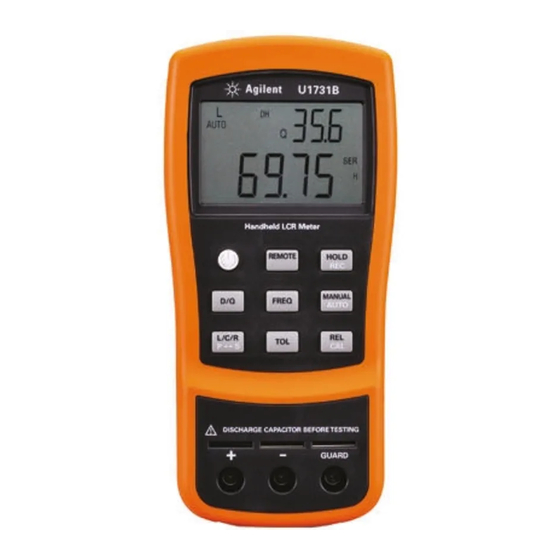
Getting Started The Front Panel at a Glance Annunciator display Keypad Input terminals U1731B U1732B Figure 1-1 Front panel of U1731B and U1732B dual display handheld LCR meter U1731B/U1732B User’s and Service Guide... -
Page 17: Display Annunciators
Reading out of HI limit Auto power off indicator TOL 1% 5% 10% 20% Tolerance mode, to set 1%, 5%, 10%, and 20% for sorting capacitance AUTO AUTO range Inductance, Capacitance, or Resistance (L,C, or R) function indicator U1731B/U1732B User’s and Service Guide... - Page 18 Unit for inductance (µH and mH) Unit for capacitance (pF, nF, µF, and mF) Remote control Special indication characters Descriptions Descriptions Indicates short connectors Indicates calibration mode Indicates damaged or open Indicates open connectors fuse U1731B/U1732B User’s and Service Guide...
-
Page 19: The Keypad At A Glance
Getting Started The Keypad at a Glance Figure 1-3 Keypad of U1731B/U1732B dual display handheld LCR meter Table 1-2 Keypad descriptions and functions No. Keys Functions Power To turn ON/OFF the instrument To select dissipation factor, quality factor, and phase angle display D/Q/θ... -
Page 20: The Input Terminal At A Glance
To avoid damaging this instrument, do not exceed the input limit. Do not apply WA R N I N G voltage to input terminals. Discharge the capacitor before testing. Figure 1-4 Input terminals/sockets of U1731B/U1732B dual display handheld LCR meter No. Terminals Functions Positive terminal/socket –... -
Page 21: Features And Functions
CAL Function Enable/Disable Auto Power-Off Low Battery Indication Backlit Display (Only Available for U1732B) Communication (Optional Accessories) This chapters provides detailed information on the features and functions that are available in the U1731B/U1732B dual display handheld LCR meter. Agilent Technologies... -
Page 22: Inductance Measurement
6 Read the display readings for inductance value and quality factor. It is recommended that you calibrate the LCR meter before testing to achieve optimum N O T E precision for all L, C, and R measurements at either the highest or lowest ranges. U1731B/U1732B User’s and Service Guide... -
Page 23: Capacitance Measurement
4 Press the FREQ key to select testing frequency. 5 Press the D/Q or D/Q/q key to select D factor for secondary display. 6 Read the display readings for capacitance value and dissipation factor. U1731B/U1732B User’s and Service Guide... -
Page 24: Resistance Measurement
3 Insert a resistor into the component receptacle socket or connect the test clip to the component leads as required. 4 Press the FREQ key to select testing frequency. 5 Read the display readings for resistance value. U1731B/U1732B User’s and Service Guide... -
Page 25: Data Hold
The D/Q/ q values can be displayed interchangeably by pressing the D/Q/ q key when the LCR meter is set to inductance or capacitance mode. This setting does not apply to resistance measurement. The phase angle mode (q) is only available for the U1732B. U1731B/U1732B User’s and Service Guide... -
Page 26: Test Frequency
LCR meter to manual ranging and cause calibration prompts to be displayed in the recommended ranges. 3 The relative mode cannot be activated if the LCR meter is set at auto-ranging with data hold activated. U1731B/U1732B User’s and Service Guide... -
Page 27: Tolerance
The LCR meter is set to auto- ranging mode by default when the meter is powered- on. For specific measurement, press AUTO/MANUAL key to select manual ranging. To return to the auto- ranging mode, press and hold the AUTO/MANUAL key for more than one second. U1731B/U1732B User’s and Service Guide... -
Page 28: Automatic Fuse Detection
For capacitance and resistance measurements, the LCR meter is set to parallel mode by default. Series mode is the default setting for inductance measurement. Press the L/C/R key for more than one second to toggle PAL and SER mode. U1731B/U1732B User’s and Service Guide... -
Page 29: Cal Function
“open cal” or “short cal”. Refer to the “Specified Note” column of any of the L, C, or R measurement from Chapter 4, “U1731B Electrical Specifications,” starting on page 26 or Chapter 4, “U1732B Electrical Specifications,” starting on page 29 to find out which of these measurement ranges are indicated with “After open... - Page 30 1 Changing measurement frequencies is handled the same way as selecting a different hardware N O T E range, and the automatic calibration prompts will be displayed in the recommended ranges. 2 Ensure that the same testing position is used after short calibration. U1731B/U1732B User’s and Service Guide...
-
Page 31: Enable/Disable Auto Power-Off
To replace the battery, refer to Chapter 3, “Battery Replacement”. Backlit Display (Only Available for U1732B) Press and the hold key for more than one second to toggle backlit ON/OFF. This function is only available for the U1732B. U1731B/U1732B User’s and Service Guide... -
Page 32: Communication (Optional Accessories)
The side with the Agilent logo must be facing up Connect to the PC’s USB port Press the snaps to remove the cable Figure 2-6 Cable connection for remote communication U1731B/U1732B User’s and Service Guide... -
Page 33: Service And Maintenance
Cleaning the LCR Meter Specification Validation This chapter describes the service and maintenance procedures for the U1731B/U1732B dual display handheld LCR meter. Repair or service that are not covered in this manual should only be performed by qualified personnel. Agilent Technologies... -
Page 34: Service
) is displayed and flashing. Use the following procedures to replace the battery. 1 Loosen screws with a suitable screwdriver and remove the battery cover as shown in Figure 3- 2 Replace the degraded battery with a new battery. U1731B/U1732B User’s and Service Guide... - Page 35 Service and Maintenance Battery cover screw Figure 3-1 Battery replacement U1731B/U1732B User’s and Service Guide...
-
Page 36: Fuse Replacement
2 Loosen screws with a suitable screwdriver and remove the bottom cover as shown in Figure 3- 3 Replace the damaged fuse with the a new fuse as specified in Chapter 4, “General Specifications”. Bottom cover screw Battery cover screw Figure 3-2 Fuse replacement U1731B/U1732B User’s and Service Guide... -
Page 37: Replacement Parts
1 Contact your nearest Agilent sales office or service center. 2 Identify the parts by the Agilent part number shown in the replaceable parts list. 3 Provide the instrument model number and serial number. Table 3-1 Replaceable parts Part Number Description A02-62-25612-2U Fuse U1731B/U1732B User’s and Service Guide... -
Page 38: Cleaning The Lcr Meter
DC adaptor. To clean the LCR meter, wipe the dirty parts with gauze or soft cloth soaked mildly in diluted neutral detergent. After cleaning, ensure that the instrument is completely dried before using. U1731B/U1732B User’s and Service Guide... -
Page 39: Specification Validation
Range (F) Test Value Used 20 µ 10 µ 200 n 100 n 20 n 10 n 200 p 100 p * Does not support test frequency of 100 Hz, 120 Hz, and 1000 Hz U1731B/U1732B User’s and Service Guide... - Page 40 Inductance (Series Mode), Test Frequency: 100 Hz, 120 Hz, 1000 Hz, or 10 kHz Recommended Equipment: GR1491 Precision Decade Inductor Range (H) Test Value Used 200 m 100 m 20 m 10 m 2000 µ 1000 µ * Does not support test frequency of 100 Hz and 120 U1731B/U1732B User’s and Service Guide...
-
Page 41: Specifications
U1731B/U1732B Dual Display Handheld LCR Meter User’s and Service Guide Specifications U1731B Electrical Specifications U1732B Electrical Specifications General Specifications SMD Tweezers Specifications This chapter contains the U1731B/U1732B dual display handheld LCR meter’s electrical and general specifications. Agilent Technologies... -
Page 42: U1731B Electrical Specifications
After open cal. * This reading can be extended up to 1999 MAX display with accuracy that is not specified. † This reading can be extended up to 19999 MAX display with accuracy that is not specified. U1731B/U1732B User’s and Service Guide... - Page 43 1.2% + 100/Lx + 5 200 mH 199.99 mH 1.0% + (Lx/10000)% +5 3.0% + 100/Lx + 5 After short cal. 20 mH 19.999 mH 2.0% + (Lx/10000)% +5 10.0% + 100/Lx + 5 After short cal. U1731B/U1732B User’s and Service Guide...
- Page 44 2 This specification is based on the measurement performed at the test socket. 3 Device Under Test (DUT) and test leads need to be properly shielded to GUARD if necessary. 4 Lx = Counts of displayed L value, e.g. L = 88.88 H then Lx = 8888. U1731B/U1732B User’s and Service Guide...
-
Page 45: General Specifications
* This specification is based on the battery operation. 1 This specification is based on the measurement performed at the test socket. N O T E 2 Device Under Test (DUT) & test leads needs to be properly shielded to GUARD if necessary. U1731B/U1732B User’s and Service Guide... - Page 46 After open cal. 2000 pF 1999.9 pF 1.0% + 5 (DF<0.1) 2.0% + 100/Cx + 5 (DF<0.1) After open cal. * This reading can be extended up to 1999 MAX display with accuracy that is not specified. U1731B/U1732B User’s and Service Guide...
- Page 47 1.2% + 100/Lx + 5 200 mH 199.99 mH 1.0% + (Lx/10000)% + 5 3.0% + 100/Lx + 5 After short cal. 20 mH 19.999 mH 2.0% + (Lx/10000)% + 5 10.0% + 100/Lx + 5 After short cal. U1731B/U1732B User’s and Service Guide...
- Page 48 2 This specification is based on the measurement performed at the test socket. 3 Device Under Test (DUT) & test leads need to be properly shielded to GUARD if necessary. 4 Lx = counts of displayed L value, e.g. L = 88.88 H, then Lx = 8888. U1731B/U1732B User’s and Service Guide...
- Page 49 Specifications General Specifications Table 4-4 General characteristics of U1731B and U1732B Parameter U1731B U1732B Power supply Single standard 9 V battery (Alkaline) External DC adaptor (DC 12 V — 15 V , Load 50 mA minimum) Display L/C/R: Maximum display 19999...
- Page 50 •3 years for main unit •3 months for standard accessories unless otherwise specified. For the main unit, Agilent's warranty also does not cover: •Damage from contamination •Normal wear and tear of mechanical components •Manuals, fuses, or standard disposable batteries U1731B/U1732B User’s and Service Guide...
-
Page 51: Smd Tweezers Specifications
4 mm shrouded plugs, which are connected to the meter's +(H- SENSE), - (L- SENSE) and GUARD ends, respectively. The length is approximately 770 mm (30.3) (see Figure 4- ± Green GUARD Hi/S Black Lo/S Figure 4-1 SMD tweezers U1731B/U1732B User’s and Service Guide... - Page 52 This tweezers is for indoor use at an altitude of up to 2,000 m. Operation temperature: 0 °C to 50 °C, R.H. 80%. Storage temperature: –20 °C to 60 °C. To avoid electrical shock, never use wet tweezers with your WA R N I N G instruments. U1731B/U1732B User’s and Service Guide...
- Page 53 Product specifications and descriptions in this document subject to change without notice. Always refer to the Agilent Web site for the latest revision. © Agilent Technologies, Inc. 2009 – 2012 Printed in Malaysia Third Edition, March 21, 2012 U1731-90059 Agilent Technologies...