
Subscribe to Our Youtube Channel
Related Manuals for Johnson Controls YORK SOLUTION LD09624


Summary of Contents for Johnson Controls YORK SOLUTION LD09624
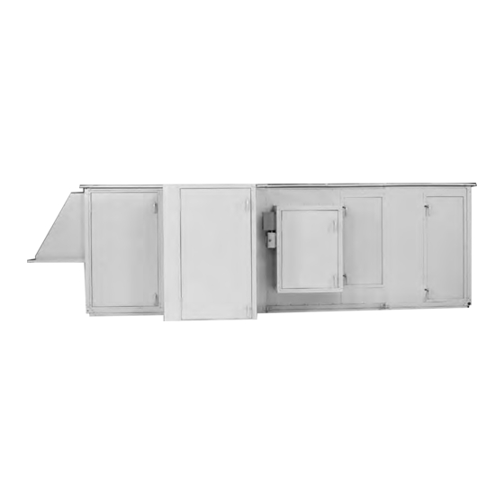
- Page 1 YORK SOlutiOn AiR hAndling unitS InstallatIon and staRtUP InstRUCtIons Supersedes 102.20-N1 (1108) Form 102.20-N1 (1109) YORK SOlutiOn indOOR And OutdOOR MOdElS LD09624 indOOR unit LD09688 OutdOOR unit...
-
Page 2: General Safety Guidelines
All wiring must be in accordance with John- son Controls published specifications and must be performed ONly by qualified Johnson Controls personnel. Johnson Controls will not be responsible for damages/problems result- ing from improper connections to the controls or application of improper control signals. -
Page 3: Changeability Of This Document
“AIR HANDLING UNITS START-UP power. CHECK LIST” Form 100.00-CL1 and file a • Contact local Johnson Controls Service for pur- copy at the local YORK Service Office. This chase of Startup Service with two weeks advance notice. Provide current job site contact. - Page 4 ForM 102.20-N1 (1109) thiS PAgE intEntiOnAllY lEFt BlAnK johNSoN coNtroLS...
-
Page 5: Table Of Contents
Check For damage ..........................1-4 Receiver Responsibility ........................1-4 indoor units ............................1-4 Outdoor units ...........................1-4 Checking for non Mounted Parts ......................1-4 StORAgE ..............................1-4 Short-term Storage ..........................1-4 long-term Storage ..........................1-5 Preventive Maintenance Prior to long term Storage ..............1-5 Periodic Fan Check ..........................1-5 johNSoN coNtroLS... -
Page 6: Table Of Contents
AiR MEASuRing dEViCE COnnECtiOnS (WhEn PROVidEd) ............2-29 Air Measuring at the Fan inlets ......................2-29 Air Measuring at unit inlets ........................2-29 PiPE ChASE inStAllAtiOn .........................2-30 tools Required ............................2-30 Materials Required ..........................2-30 Procedure ............................2-30 Condensate drain Arrangement ....................2-35 ElECtRiCAl - gEnERAl ........................2-36 johNSoN coNtroLS... - Page 7 Direct Expansion Coils (DX) ....................2-54 DX Coil Types ..........................2-55 Combined Coil types .......................2-55 DX Coil Circuiting ........................2-55 DX Coil Circuiting And Staging ....................2-57 Thermostatic Expansion Valves (TXV) ...................2-59 hot gas Bypass ..........................2-59 Maintaining Adequate Airflow ....................2-59 VAV Systems ..........................2-59 johNSoN coNtroLS...
- Page 8 2” and 4" Prefilter in Combination With a Double Header Final Filter...2-72 installation of Spring latches ....................2-72 Installation of Prefilter Latches ....................2-72 hEPA Filters ............................2-74 Welded Bevel Seal Frame ......................2-74 Visual Control Filter Clamps ....................2-74 johNSoN coNtroLS...
- Page 9 ............................3-11 identify the unit type ........................3-11 Preliminary Coordination ......................3-12 tools Recommended ........................3-12 Air handler Pre Start Checks ......................3-12 Burner Pre Start Checks .......................3-12 Burner Start-up Procedure ......................3-14 Condensate drain Arrangement ....................3-15 Electric heat Startup ...........................3-25 Airflow Requirements ........................3-25 johNSoN coNtroLS...
- Page 10 ForM 102.20-N1 (1109) thiS PAgE intEntiOnAllY lEFt BlAnK johNSoN coNtroLS...
-
Page 11: List Of Figures
FIG. 2-23 – ASSEMBLY OF END CHANNEL SHIPPING SPLIT (EXPANDED CABINET) .....2-18 Fig. 2-24 – REMOVE And REPOSitiOn ShiPPing SPlit AnglE.............2-18 Fig. 2-25 – PlACing And AnChORing FiRSt SECtiOn And AttAChing COME-A-lOngS ..2-19 Fig. 2-26 – REMOVE liFting lugS And SAVE hARdWARE ............2-19 Fig. 2-27 – ElECtRiCAl COnnECtiOnS.....................2-19 johNSoN coNtroLS... - Page 12 Fig. 2-65 – PiPE ChASE EnClOSuRE ....................2-44 Fig. 2-66 – FACtORY COil COnnECtiOnS ..................2-44 Fig. 2-67 – StAggEREd COil COnFiguRAtiOnS ................2-45 Fig. 2-68 – ChillEd WAtER COil COnnECtiOnS ................2-46 Fig. 2-69 – hOt WAtER PiPing - 2 WAY VAlVE ..................2-47 johNSoN coNtroLS...
- Page 13 FiltER tO thE FRAME.....................2-69 Fig. 2-103 – inStAllEd CARtRidgE FiltER ..................2-70 Fig. 2-104 – inStAll lAtCh P//n 026-35778-007 ................2-70 Fig. 2-105 – inStAllEd CARtRigE W/PlEAtS ..................2-70 Fig. 2-106 – CORRECt uSE OF KnOCKOutS ..................2-71 Fig. 2-107 – CORRECt lAtCh/KnOCKOut COnFiguRAtiOn............2-71 johNSoN coNtroLS...
- Page 14 Fig. 3-24 – tYPiCAl WiRing diAgRAM ....................3-22 Fig. 3-25 – MiniMuM AiR VElOCitY REQuiREd FOR SAFE OPERAtiOn ........3-25 Fig. 3-26 – PRESSuRE PROBE diRECtiOn ..................3-26 Fig. 3-27 – AiRFlOW SWitCh COnnECtiOnS ...................3-26 Fig. 3-28 – AiR hAndlER StARt-uP ChECKliSt ................3-27 johNSoN coNtroLS...
- Page 15 3-1 – tORQuE FOR tightEning SEtSCREWS ...............3-3 tABlE 3-2 – nAtuRAl gAS PRESSuRE REQuiREMEntS (inChES WC) ........3-18 tABlE 3-3 – PiPE SiZE REQuiREd .......................3-19 tABlE 3-4 – BuRnER tEPERAtuRE RiSE ..................3-23 tABlE 3-5 – inSPECtiOn REQuiREMEntS ..................3-29 johNSoN coNtroLS...
- Page 16 ForM 102.20-N1 (1109) thiS PAgE intEntiOnAllY lEFt BlAnK johNSoN coNtroLS...
-
Page 17: Introduction
This manual has been prepared as a guide for installing, operating and maintaining YORK Solution The operation of these units can be divided into sys- Air Handling Units. Johnson Controls has produced a tems: quality product that is adaptable to almost any comfort 1. -
Page 18: Economizer System - Typical
(rh) coiL coNNectioN LeFt haND (Lh) coiL coNNectioN retUrN air oUtSiDe air lEFt iNLet SectioN Drive haND aND coiL haND DeterMiNeD BY FaciNG the iNLet SectioN FROnt LD08004 Fig. 2 – unit And COil hAnd idEntiFiCAtiOn johNSoN coNtroLS... -
Page 19: Segment Identification
• iC – integral FaCe & BypaSS Coil • at – attenuator • ig – indireCt gaS Fired FurnaCe • hm - humidiFier • eh – eleCtriC heater • uv - uvC lampS EnERgY RECOVERY • er – energy reCovery johNSoN coNtroLS... -
Page 20: Table 2 - Unit Nomenclature
ForM 102.20-N1 (1109) tABlE 2 – unit nOMEnClAtuRE johNSoN coNtroLS... -
Page 21: Unit Identification
(Skid 4 of 5) (Skid 2 of 5) (FR) (FS)(CC-HM)(XA-IC-XA-RF)(EE) 9800071 Direction of Airflow lD11728A FIG. 3 – UNIT ID LABEL Order of Assembly * See Table 1 for Segment Identi cation lD11752A FIG. 5 – SEGMENT ID BOX EXAMPLE johnson controls... -
Page 22: Loose Component Id Label
UNIT TAG Hood AHU 9-10 JOB NAME SKID OVERALL SIZE Owens Corning BLDG-21 116 H x 180 W x 85 L AHU 9-10 one of six hoods installed on (ee) skid/segment. LD11751a Fig. 6 – lOOSE COMPOnEnt id lABElS johNSoN coNtroLS... -
Page 23: 1.0 Pre-Installation
Johnson Controls will NOT be respon- sible for any damage or loss of parts SHIPPED lOOSE DAMPERS. When in shipments or at the job site. Re-... -
Page 24: Off-Loading
Johnson Controls Sales representative if you have unit casing (see Fig. 1-1). When lifting long units a any questions regarding unit weights. -
Page 25: Shackles
Do not lift by corners. LD13768 Fig. 1-5 – PROPER liFting With ShACKlE At liFting lug LD13767 Fig. 1-4 – PROPER liFting With ShACKlE At CORnER LD13766 Fig. 1-6 – RECOMMEndEd liFting With BASERAil johNSoN coNtroLS... -
Page 26: Inspection
It is Johnson Controls intention that a shipping wrapper rodents. The units must be protected from con- be applied to unpainted indoor units for protection stant exposure to rain and snow. -
Page 27: Long-Term Storage
If long-term storage six (6) months from date of shipment. If long-term is anticipated, contact Johnson Con- storage is anticipated, contact the Johnson Controls trols Sales representative at time of Sales representative for the proper instructions and order entry for the proper instructions requirements for long-term storage. -
Page 28: Fig. 1-7 - Long-Term Storage Requirement - Field Preparation
Pre-installation ForM 102.20-n1 (1109) FIG. 1-7 – LONG-TERM STORAGE REQUIREMENT - FIELD PREPARATION, FORM 50.23-NM3 johnson controls... -
Page 29: Fig. 1-8 - Long-Term Storage Periodic Checklist And Logs
ForM 102.20-n1 (1109) FIG. 1-8 – LONG-TERM STORAGE PERIODIC CHECKLIST AND LOGS, FORM 50.23-CL3 johnson controls... - Page 30 ForM 102.20-N1 (1109) thiS PAgE intEntiOnAllY lEFt BlAnK johNSoN coNtroLS...
-
Page 31: 2.0 Installation
Inlet Section Rain Hood (add to unit width or length) UNIT WIDTH Pipe Chase Enclosure (add to unit width) Coil Access Panel on Outdoor Unit (allow clearance = to unit width) Fig. 2-1 – MiniMuM SERViCE ClEARAnCES LD6328-4 johNSoN coNtroLS... -
Page 32: Mounting
Be sure the supporting structures will not obstruct the duct, piping or wiring connections. johNSoN coNtroLS... -
Page 33: Steel Frame
3. Attach curb walls together to form rectangular Pipe Chase Curb location: perimeter as shown, leaving bolts loose. Unit submittal drawing package has a Johnson Controls curb drawing After the curb is set in place, ensure showing dimensions of curb and pipe proper consideration has been given chase. -
Page 34: Fig. 2-2 - Typical Curb Assembly
Contractor is responsible for providing ductwork to include Base Rail height. 4. If curb space used as plenum, Seal all joints and seams with suitable sealer such as urethane caulk (YORK P/N 013-02966-011) LD09616G Fig. 2-2 – tYPiCAl CuRB ASSEMBlY johNSoN coNtroLS... -
Page 35: Clearance
Pad The housekeeping pad must be flat and level (see Fig's 2-3, 2-4 and 2-5). LD05372 Fig. 2-3 – nO BASERAil – hOuSEKEEPing PAd REQuiREd tO ACCOMMOdAtE tRAP hEight LD05374 Fig. 2-5 – With BASERAil And hOuSEKEEPing johNSoN coNtroLS... -
Page 36: Ceiling Suspended Units
Refer to Fig. 2-6 “Ceiling Suspended Unit” for proper support of unit in the direction of airflow and/or perpendicular to the direction of airflow. general Requirements Johnson Controls recommends that ceiling suspension of units be accomplished in the field with the following: Structure positioned perpendicular to airflow... -
Page 37: Unit Installation
Gaskets on curbs can pose a problem when sliding sec- tions together for the final connection of each shipping split. LD09613 Fig. 2-7 – tOOlS tYPiCAllY uSEd FOR ASSEMBlY OF ShiPPing SPlitS johNSoN coNtroLS... -
Page 38: Ship Loose Parts
(assembled) 3/8" Flat Washer LD13349 3/8" Lock Fig. 2-11 – tOP RACEWAY SPlit FAStEnER PACK Washer LD11030a P/n 386-04747-000 (2 each per pack) Fig. 2-9 – BOttOM RACEWAY ShiPPing SPlit FAStEnER PACK P/n 386-03418-000 (4 each per pack) johNSoN coNtroLS... -
Page 39: Fig. 2-12 - Pipe Chase, Hoods & Seam Caps
Apply Caulk Apply Caulk PIPE CHASE BASERAIL COVER HOOD P/N 086-23998-001 • 1/4"-14 x 1" Hex Head w/ Washer & Gasket Tek Screw • 3/16" x 3/4" Butyl Tape LD13770a Fig. 2-12 – PiPE ChASE, hOOdS & SEAM CAPS johNSoN coNtroLS... -
Page 40: Fig. 2-13 - Miscellaneous Parts For Options
DO NOT touch UV lamps (tubes) with bare hands or leather gloves as LD13788 oils will damage the tubes. Use clean cotton rags, clean jersey or latex gloves to handle the lamps (tubes). Fig. 2-13 – MiSCEllAnEOuS PARtS FOR OPtiOnS 2-10 johNSoN coNtroLS... -
Page 41: Fig. 2-14 - Hardware, Gasketing, Caulk, Paint And Tape
PHILLIPS PAN HEAD SELF DRILLING SCREW P/N 021-19560-000 1/4”-14 X 1” SPARE FAN BELT HEX HEAD (Attached to Fan) SELF DRILLING SCREW W/ EDPM WASHER P/N 021-30530-052 LD13771 Fig. 2-14 – hARdWARE, gASKEting, CAulK, PAint And tAPE 2-11 johNSoN coNtroLS... -
Page 42: Fig. 2-15 - Shipping Split Examples
BASE CHANNEL BASE CHANNEL 3/4" GR5 HEX BOLT (use from Lifting Lug) 3/4" ZINC HEX NUT (use from Lifting Lug) (no flat or lock washers required) LD14263 Fig. 2-16 – SHIPPING SPLIT EXAMPLES FOR EXPANDED CABINET 2-12 johNSoN coNtroLS... -
Page 43: Assembly Of Outdoor Unit
Remove plastic shipping covers and their supports. d) Remove screws from curb rest to release wood shipping blocks. Leave blocks under unit sections until lifted. Be sure that no debris clings to the bottom of each section when lifted for placement. 2-13 johNSoN coNtroLS... -
Page 44: Fig. 2-17 - Applying Gasket
All lighting and 3-phase wires must corners. be hard wired when no plug-ins are 5. Apply a ½" thick bead of caulk to curb top surface provided. only where the next section will be placed, plus about 4". 2-14 johNSoN coNtroLS... -
Page 45: Fig. 2-19 - Remove And Reposition Shipping Split Angle
8. Attach the power pulls or come-a-longs to the far end of the next section. 11. Fasten bottom lifting lugs together using 1/2" x 4" bolts provided. 12. Fasten top raceway bracket using 1/2" x 5-1/2" bolts. 2-15 johNSoN coNtroLS... -
Page 46: Fig. 2-20 - Bringing Sections Together
Painted seam caps are applied over the joints on raceway corners. the sides and roof of the exterior and galvanized Only needed on units or sections with- seam caps are applied on the floor of the interior out baserails. only. 2-16 johNSoN coNtroLS... -
Page 47: Assembly Of Indoor Unit
See “Ship loose Parts” to identify gaskets and hardware items. If the unit or unit sections are too large to fit through an opening, contact the local Johnson Controls office for assistance. Technical instruction is LD13779 available for Disassembly and Reas- sembly. -
Page 48: Fig. 2-23 - Assembly Of End Channel Shipping Split (Expanded Cabinet)
LD14097 Fig. 2-24 – REMOVE And REPOSitiOn ShiPPing SPlit AnglE 2-18 johNSoN coNtroLS... -
Page 49: Fig. 2-25 - Placing And Anchoring First Section And Attaching Come-A-Longs
If any will not be accessible, assemble to unit. the electrical connectors and/or pneumatic tubes each according to their labels before joining of sections is complete. Refer to Fig. 2-27. 2-19 johNSoN coNtroLS... -
Page 50: Fig. 2-28 - Installing Bolts After Pulling Units Tight Together
4" bolts provided. See Fig. 2-28. LD13781 Use come-a-longs to pull the sections together. The bolts are to hold the sections tight after they are pulled together. Fig. 2-28 – inStAlling BOltS AFtER Pulling unitS tight tOgEthER 2-20 johNSoN coNtroLS... -
Page 51: Installation Of Tiered Unit
If top tier has shipping splits, refer to “Installing Multiple Piece Indoor Unit” for correct assembly procedure. LD09625 3/8" Flat Washer Size = 3/16" 3/8" Lock Washer Allen Wrench LD11029a Fig. 2-30 – tiEREd unit SECuREd With BRACKEtS 2-21 johNSoN coNtroLS... -
Page 52: Fig. 2-32 - Guiding Brackets Together
9. Secure the top tier to bottom tier with 3/8" x .75" Allen head bolts. 10. Install 1-1/2" Corner Connector Plugs in bottom raceway corners. Only needed on units or sections with- out baserail 2-22 johNSoN coNtroLS... -
Page 53: Assembly Of End Channel Shipping Split
3/16" ALLEN HEAD SCREWS IN RACEWAY CORNERS AT ENDS OF ALL SEGMENTS DETAIL A JOINING TOGETHER; MUST BE REMOVED PRIOR TO PULLING SECTIONS TOGETHER. LD12357 (EnERgY RECOVERY WhEEl ShOWn) Fig. 2-33 – ASSEMBlY OF End ChAnnEl ShiPPing SPlit 2-23 johNSoN coNtroLS... -
Page 54: Hood Installation With Optional Mist Eliminators
The contractor is to find them secured with tape inside bottom of the hood should extend approximately 6" below the opening in the unit panel. and put them through their respective penetration to the exterior and mount them to the bracket provided. 2-24 johNSoN coNtroLS... -
Page 55: Actuator Installation
JACKSHAFT TO BLADE LINKAGE DAMPER SELF ACTUATOR DRILLING ACTUATOR SCREWS SHAFT CLAMP BEARING PLATE EDGE CLIP 025-39067-002 ROTATION SELECTOR MOUNTING GROOVES MOUNTING BKT JACKSHAFT ACTUATOR MANUAL CRANK SPRING HOSE CLAMP(S) LD12144 Fig. 2-35 – diRECt COuPlEd On JACKShAFt 2-25 johNSoN coNtroLS... -
Page 56: Installation Of Multizone (Mz) Dampers
HOT DECK MOUNTING DAMPER FLANGES aCtUatoR toRQUE BRaCKEt FACTORY SMALL 025-39032-002 35 IN LBS 086-03474-516 INSTALLED COUPLER 086-03474-516 (Top Disch.) LARGE 025-30958-008 133 IN LBS 086-03474-517 (Rear Disch.) COLD DECK DAMPER LD12029a Fig. 2-36 – MZ dAMPER/ACtuAtOR ASSEMBlY 2-26 johNSoN coNtroLS... -
Page 57: Actuator Installation Mutlizone (Mz) - Field Supplied
All required steam supply piping, condensate piping and wiring are the responsibility of the installing contractor(s). DAMPER SHAFT EXTENSION KIT P/N 026-33715-002 LD13784 Fig. 2-37 – DAMPER SHAFT EXTENSION KIT 2-27 johNSoN coNtroLS... -
Page 58: Uvc Emitter Lights
(tube) 90 degrees. inside the module with one hand and straightening up the other end of the lamp with your other hand until you hear the click. Fig. 2-38 – V-MOd inStAllAtiOn Fig. 2-40 – V-FLEX INSTALLATION 2-28 johNSoN coNtroLS... -
Page 59: Air Measuring Device Connections (When Provided)
The positive transducer are not provided unless factory packaged (+) port is left open to the fan section. Wiring is not controls were selected. provided to the transducer unless factory packaged controls were selected. 2-29 johNSoN coNtroLS... -
Page 60: Pipe Chase Installation
Before installing pipe chase, remove overlap vertical gaskets in all four any self-drilling screws from the top corners (see Fig. 2-42). and bottom raceway and side panel that may interfere with the installation of the pipe chase or trim angles. 2-30 johNSoN coNtroLS... -
Page 61: Fig. 2-42 - Apply Gasket To Pipe Chase
Apply caulking to all exterior joints between pipe chase. Use 1/4"-14 x 1" hex head self- pipe chase and air handler baserails (when drilling screws (see Fig. 2-44). purchased) (see Fig. 2-45). 2-31 johNSoN coNtroLS... -
Page 62: Fig. 2-45 - Baserail Caulk Application
(see Fig. 2-46) Notch on cover angle must be on the (No caulking required here.) air handler side (see Fig. 2-48). 5. Install the Cover Angles (See Fig. 2-48) 2-32 johNSoN coNtroLS... -
Page 63: Fig. 2-49 - Proper Positioning Of Cover Angle With Notch On Air Handler Side
APPLY CAULK AROUND OF COVER AS SHOWN PERIMETER OF PART prevent condensation entering build- BELOW. BEFORE APPLYING TO ing. BASERAIL SEAM. 2) APPLY COVER TO BASERAIL SEAM. PIPECHASE BASERAIL COVER LD12032B Fig. 2-51 – BASERAil COVER APPliCAtiOn 2-33 johNSoN coNtroLS... - Page 64 ForM 102.20-N1 (1109) 2-34 johNSoN coNtroLS...
-
Page 65: Condensate Drain Arrangement
2. Be sure the air handler is installed at an elevation that enables proper condensate drainage and trap- ping dimensions as provided in Fig.2-53. Mini- mum trap dimensions MUST be accommodated. 2-35 johNSoN coNtroLS... -
Page 66: Electrical - General
Many of the con- nections contain several strands of wire, and while they were tightened at the time of assembly, they should be checked and re-tightened if needed. The danger of a poor connection is overheating and component failure. 2-36 johNSoN coNtroLS... -
Page 67: Power Connections
Refer to Motor Data Nameplate for all motor specifications (see Fig. 2-54). LD11591 Fig. 2-55 – tYPiCAl POWER WiRing OF EnERgY RECOVERY WhEEl 00495vip Fig. 2-54 – tYPiCAl MOtOR dAtA / nAMEPlAtE 2-37 johNSoN coNtroLS... -
Page 68: Gas Heat Option
Inside of XTO Gas Draft Damper Burner Pipe Chase. Adjustable Quadrant Safety Limits ID Fan ID Fan Motor Burner Control Panel (contains Factory Test Data Sheet, Manufacturers IOM and Burner Control System.) LD11596B Fig. 2-56 – gAS BuRnER COMPOnEnt lOCAtiOnS 2-38 johNSoN coNtroLS... -
Page 69: Electric Heat Option
The danger of a poor connection is overheating and component failure. LD11594a DO NOT PENETRATE any main or auxiliary drain pan. Fig. 2-58 – tYPiCAl ElECtRiC hEAt COntROl PAnEl intERiOR WiRing And COMPOnEntS 2-39 johNSoN coNtroLS... -
Page 70: Available Control Options
If ping. a minimum value of 10 megohms is not achieved then any damaged elements or ceramic insulators must be replaced prior to operation. 2-40 johNSoN coNtroLS... -
Page 71: Fig. 2-60 - Pressure Probe Direction
NEGATIVE PRESSURE / AIR DRAWN THROUGH HEATER BLOWER HEATER AIRFLOW PICK UP TUBE TOWARDS BLOWER ATTACHED TO “LOW” PORT OF AIRFLOW SWITCH LD14268 Fig. 2-60 – PRESSuRE PROBE diRECtiOn MOUNTING BRACKET HIGH PORT LOW PORT LD14270 Fig. 2-61 – AiRFlOW SWitCh COnnECtiOnS 2-41 johNSoN coNtroLS... -
Page 72: Electrical Installation
Table 310-15(b)(2)(a). heater nameplate Kw number of heated sections x MAXIMUM CURRENT FOR COPPER WIRING area of one heated section AMPS WiRE AMPS WiRE AMPS WiRE SiZE SiZE SiZE AWg/ AWg/ AWg/ 125% 100% 125% 100% 125% 100% 2-42 johNSoN coNtroLS... -
Page 73: Humidifier Option (Electric)
IOM found inside control panel or attached. Factory package control drawings may not include humidifier points. If humidifier IOM cannot be located inside humidifier, call Johnson Controls Airside Product Support for information on receiving an electronic version of the IOM. LD11726 Fig. -
Page 74: Piping Connections
OUTDOOR: DRAIN CONNECTION IS ALWAYS ON SIDE OPPOSITE PIPE CHASE. LD09629a usable working clearance is approximately the depth of the pipe chase minus 5". all dimensions are approximate and not certified for construction. Fig. 2-65 – PiPE ChASE EnClOSuRE LD06340-1 Fig. 2-66 – FACtORY COil COnnECtiOnS 2-44 johNSoN coNtroLS... -
Page 75: Coil Piping
StAggEREd COil – AnglE WAll StAggEREd COil – OPPOSitE SidE COnnECtiOnS Fig. 2-67 – StAggEREd COil COnFiguRAtiOnS 2-45 johNSoN coNtroLS... -
Page 76: Water
RETURN UNION COIL SUPPLY STRAINER CHILLED REDUCING DRAIN WATER SUPPLY GLOBE UNION VALVE RETURN COIL SUPPLY GATE PLUG VALVE GATE VALVE W/ LD12939 HOSE BIB Example - NOT for construction Fig. 2-68 – ChillEd WAtER COil COnnECtiOnS 2-46 johNSoN coNtroLS... -
Page 77: Fig. 2-69 - Hot Water Piping - 2 Way Valve
WATER DIVERTING VALVE SUPPLY GLOBE 1 Inlet, 2 Outlets UNION VALVE RETURN COIL SUPPLY GATE PLUG VALVE GATE VALVE W/ HOSE BIB LD13792 Example - NOT for construction Fig. 2-70 – hOt WAtER PiPing With diVERting VAlVE 2-47 johNSoN coNtroLS... -
Page 78: Water Treatment
Refer to Fig. 2-71 “Steam Coil Piping Arrangements.” Steam Coils The operation of steam coils is dependent on airflow quantity and temperature. Consult the submittal issued for each specific unit for above information. 2-48 johNSoN coNtroLS... -
Page 79: Steam Traps
12" MIN. COILS IN SERIES AIR FLOW MUST HAVE COILS IN PARALLEL AIR FLOW INDIVIDUAL TRAPS AND CONTROL VALVES MAY HAVE COMMON SUPPLY AND SINGLE TRAP (INDIVIDUAL COIL TRAP PREFERRED) LD04887a Fig. 2-71 – StEAM COil PiPing ARRAngEMEntS 2-49 johNSoN coNtroLS... -
Page 80: Vifb And Ifb
STEAM OUT prior to use. LD09631 See IFB/VIFB manufacturer's IOM for additional piping details. Fig. 2-73 – VERtiCAl intEgRAl FACE And BYPASS COil Factory does NOT pipe connections to (FACE MOuntEd ACtuAtOR ShOWn) unit exterior. 2-50 johNSoN coNtroLS... - Page 81 24" downstream of leaving edge of VIFB/ reduce only at trap. Do not use reducing bushing on IFB casing. Low limit element must cross both face coil return connection. and bypass areas, parallel to headers. 2-51 johNSoN coNtroLS...
-
Page 82: Fig. 2-74 - Hot Water Piping For 2 Row Coil Vifb
DRAINS LD09632 Fig. 2-74 – hOt WAtER PiPing FOR 2 ROW COil ViFB 3/4" (19.1) AUTOMATIC AIR VENT IN TOP HEADER HOT WATER RETURN HOT WATER SUPPLY DRAIN LD09633 Fig. 2-75 – hOt WAtER PiPing FOR iFB 2-52 johNSoN coNtroLS... -
Page 83: Fig. 2-76 - Steam Piping For Vifb Coil
PARALLEL TO COIL HEADER AND INVERTED RETURN MAIN AS CLOSE AS POSSIBLE TO COIL BUCKET CONDENSATE CONNECTION. TRAP NOTE : DIMENSIONS ARE IN INCHES. DIMENSIONS IN PARENTHESIS ARE IN MILLIMETERS. LD09634 Fig. 2-76 – StEAM PiPing FOR ViFB COil 2-53 johNSoN coNtroLS... -
Page 84: Refrigeration
Insulate P-trap from street fittings bulb / line after clamping bulb to line. to maintain minimum trap volume. LD05171a FIG. 2-77 – TYPICAL PIPING AND SUNDRIES AT THE DX COIL 2-54 johNSoN coNtroLS... -
Page 85: Dx Coil Types
SQ optional designs. The coil designs fall into the two following categories. FACE SPLIT ROW SPLIT INTERLACED REFRIGERANT IN LEGEND REFRIGERANT OUT WARM AIR COLD AIR LD13319B FIG. 2-78 – DX COIL CIRCUITING TYPES 2-55 johNSoN coNtroLS... -
Page 86: Fig. 2-79 - Non-Stacked Coil Design - Sq Special
Contact Coil Marketing for other arrangements not shown. Face-split DX coils must be config- ured to provide full-face coverage at all condensing unit load steps. Johnson Controls assumes no re- 2 Distributor 1 Distributor Circuits 50 - 50% Circuit... -
Page 87: Dx Coil Circuiting And Staging
Circuits Row Split Circuits Face Split Circuits Row Split 66-33 Split Interlaced Row Split & Interlaced & Face Interlaced SQ Required SQ Required SQ Required SQ Required LD09146 Fig. 2-82 – StACKEd COil dESignS - SQ SPECiAl 2-57 johNSoN coNtroLS... -
Page 88: Fig. 2-84 - One Coil Circuit Perrefrigerant Circuit
In the case of a stacked coil with four coil circuits piped to a condenser with six compressors, the coil circuits would be face-split and interlaced with two interlaced circuits on the lower coil section and two on the upper (Fig. 2-89). 2-58 johNSoN coNtroLS... -
Page 89: Thermostatic Expansion Valves (Txv)
VAV system the air temperature remains constant and the air volume is suction pressure control, but it provides better capacity varied to meet the cooling requirements. control at low loads. 2-59 johNSoN coNtroLS... - Page 90 Under any circumstances, a minimum of 350 FPM in response. The change in supply air volume is face velocity across the coil must be maintained for accomplished using a Variable Frequency Drive or DX split systems. similar device. 2-60 johNSoN coNtroLS...
-
Page 91: Condensate Drain Piping
DRAIN PAN connection. LD05371-2 NO. 3 - FAN RUNNING AND CONDENSATE LD06342-1 Fig. 2-92 – tRAP dEtAil FOR BlOW thROugh Fig. 2-90 – dRAin tRAP ShOWing WAtER lOCAtiOn duRing dRAW thROugh APPliCAtiOn OPERAtiOn StAgES 2-61 johNSoN coNtroLS... -
Page 92: Elevating Unit For Gravity Floor Drain Connections
3", 6", 8" and 10" heights. Contractor is responsible for providing ductwork to include baserail height. Effective Duct Length All ductwork should be supported in- dependently from the unit. LD06335-2 Fig. 2-94 – RECOMMEndEd diSChARgE duCt ARRAngEMEnt WhEn tuRnS ARE REQuiREd 2-62 johNSoN coNtroLS... -
Page 93: Duct Connections
DETAIL A SHEET METAL SCREW GASKET OR SEALANT GASKET OR SEALANT FLANGED DUCT RAW EDGE DUCT BOTTOM VIEW OF UNIT LD14087 Fig. 2-95 – RECOMMEndEd diSChARgE duCt ARRAngEMEnt WhEn tuRnS ARE REQuiREd 2-63 johNSoN coNtroLS... -
Page 94: Sound And Vibration Transmission
Fig. 2-97 – ROOF tO duCt inStAllAtiOn - • Duct systems should not be pressurized without hORiZOntAl diSChARgE sufficient time for curing of sealant systems. Fol- low sealant manufacturer's recommendations for application of the sealant. 2-64 johNSoN coNtroLS... -
Page 95: Air Filters
Bag Filter Most YORK Solution air handling units will be 12" Cartridge shipped without filters. The Johnson Controls Sales office is responsible for the order and delivery of filters in a timely manner. It is important for the contractor Cartridge or commissioning agent to be in touch with Johnson Controls regarding this issue. -
Page 96: Filter Latches
(t. SectioN) (T. SECTION) Used with 2” and 4" Prefilter in combination with a Double Header Final Filter and Varicel DH Double Used to attach HEPA Filters to Holding Frame. Headered Filter. Fig. 2-98 – FiltER lAtChES 2-66 johNSoN coNtroLS... - Page 97 026-35778-006 & 026-36339-000 FiltER FRAME 24X24 - 16 ga. Galvanized p/n 026-35778-007 & 026-35778-000 p/n 026-35778-006 & 026-36339-001 p/n 026-35778-007, 026-35778-008 & 026-35778-000 p/n 026-35778-006 & 026-36339-000 note: typically when filters are by others, so are the filter clips. 2-67 johNSoN coNtroLS...
-
Page 98: Installation Of 2" Perfectpleat, Premium Or Premium Hm
3 The latch installation should now be complete. The latch should now be “trapped” within the three (3) knockouts, but should be able to freely rotate (see Fig.2-99). LD010174 Fig. 2-100 – FullY inStAllEd FiltER LD010171 Fig. 2-99 – CORRECtlY inStAllEd lAtCh P/n 026-35778-000. 2-68 johNSoN coNtroLS... -
Page 99: Installation Of Spring Latches
Fig. 2-102 – PlACE thE End OF thE lAtCh latches. OVER thE FiltER FRAME, SECuRing thE FiltER tO thE FRAME. 6. The filter should now be securely installed into the frame. LD010177 Fig. 2-101 – CORRECtlY inStAllEd lAtCh P/n 026-35778-007 2-69 johNSoN coNtroLS... -
Page 100: Installation Of Sh Single Headered Filters
6. The filter should now be securely installed into the latches. 4. The filters should now be securely installed into frame (see Fig.2-103). the frame, as shown in Fig.2-105. LD010148 LD010160 Fig. 2-103 – inStAllEd CARtRidgE FiltER Fig. 2-105 – inStAllEd CARtRigE W/PlEAtS 2-70 johNSoN coNtroLS... -
Page 101: Installation Of A Varicel Dh Double Headered Filter
“trapped” within the three (3) frame. knockouts. LD010184 Fig. 2-109 – SPRing lAtCh ShOuld BE PullEd LD010154 And FAStEnEd in hOlE in thE Fig. 2-107 – CORRECt lAtCh/KnOCKOut hEAdER OF thE FiltER. COnFiguRAtiOn. 2-71 johNSoN coNtroLS... -
Page 102: Installation Of A 2" And 4" Prefilter In Combination With A Double Header Final Filter
(see Fig.2-110). leg. The prefilter latch should be slid over the header as shown in Fig.2-112. LD010163 LD010154 Fig. 2-112 – PREFiltER lAtCh AFtER Fig. 2-110 – CORRECt lAtCh/KnOCKOut inStAllAtiOn OntO FiltER COnFiguRAtiOn. P/n 026-35778-006 hEAdER. 2-72 johNSoN coNtroLS... -
Page 103: Fig. 2-113 - Position Prefilter In Front Of The Final Filter
Fig.2-115. LD010190 Fig. 2-114 – SPRing thE End OF thE lAtCh SO thAt it FitS OVER thE EdgE OF thE PREFiltER. (4" W/026-36339-000 lAtCh ShOWn) 2-73 johNSoN coNtroLS... -
Page 104: Hepa Filters
SINGLE FILTER CLAMPS (PERIMETER) 2" 2" 2" DOUBLE SILVER FILTER T-SECTION PERIMETER SECTION - CLAMPS TYPE H (T. SECTION) LD06647a Fig. 2-116 – hEPA FiltER FRAME CROSS LD06648-1 SECtiOn ViEW Fig. 2-117 – ViSuAl COntROl FiltER ClAMPS 2-74 johNSoN coNtroLS... -
Page 105: Fig. 2-118 - Hepa Filter Installation
(ADJUST BOLT HEAD FLUSH WITH CLAMP) SPRING DUCTWORK AIRFLOW BEVEL SEAL CELL SIDE FRAME (PERIMETER EXTRUSION) MEDIA PACK BEVEL SEAL FRAME GASKET BEVEL RECESSED SEALING CELL SIDE SURFACE LD06646a Fig. 2-119 – WEldEd BEVEl SEAl FiltER inStAllAtiOn 2-75 johNSoN coNtroLS... - Page 106 ForM 102.20-N1 (1109) thiS PAgE intEntiOnAllY lEFt BlAnK 2-76 johNSoN coNtroLS...
-
Page 107: 3.0 Startup
• Wi t h o u t p r o p e r c o n t r o l o f perature) with gas heat venting]. dampers. • With smoke dampers closed. • During a fire alarm or smoke purge test. • Any airflow restriction greater than normal. • Fluctuating or incorrect voltage power supply johNSoN coNtroLS... -
Page 108: Pre Start-Up
Fig. 3-1 – tERMinAtiOn ChARt inSidE 16. Verify all shipping splits sealed and secured prop- EnClOSuRE dOOR erly. 17. Verify pipe chase floor sealed at penetrations. 18. Verify all shipping bolts and other materials have been removed. johNSoN coNtroLS... -
Page 109: Pre Start Up Fan Assembly Inspection
Recheck tension after one day and Fig. 3-3 – OdP (OPEn dRiP PROOF) three days. c) Ensure motor mounting bolts and adjustable motor base bolts are tight. 5. Verify tie down bolts removed from 4 corners of fan base assembly. johNSoN coNtroLS... -
Page 110: Isolators
3. Verify the fan is aligned with unit discharge. 4. Re-adjust as necessary with isolators. LDO9637 Fig. 3-5 – SPRing iSOlAtOR 2. For thrust restraint adjustment procedures, when applied, (see IOM Section 5.0). 3. Fig. 3-6 shows isolator with seismic snubber re- straint option. johNSoN coNtroLS... -
Page 111: Start-Up
Linkage design and/or damper linkage may not be complete Start-up as outlined in this provided by Johnson Controls. Airflow control guide. Do not allow the unit to run dampers may be operated with pneumatic or electric on temporary power that is not reliable actuator/controllers. -
Page 112: Typical Actuators Locations
Typical Actuators Locations With the actuator shaft clamp tightened to the damper jackshaft, and the damper shaft is completely rotated Johnson Controls standard actuators are direct coupled to its proper position, manually operate the actuator to on damper jackshaft. its fully actuated position using the crank arm provided Basic Actuators Installation with the actuator. -
Page 113: Energize Fan Motor(S)
If the skip frequencies are not avail- able to the installing contractor, the contractor must have the fan analyzed by a professional balancer before the VFD can be set and power is supplied to the fan. FIG. 3-7 – EXAMPLE OF SWEEP BALANCE RESULTS johNSoN coNtroLS... -
Page 114: Check Doors And Latches For Proper Adjustment
- Job ID number from YORK Solution Unit ID Label. • A new driver (motor) sheave or sheave and bush- ing are usually all that is required to directly replace the present adjustable driver sheave. Fig. 3-8 – tYPiCAl dRiVE Kit dAtA tAg johNSoN coNtroLS... -
Page 115: Energy Recovery Wheel
COIL ENERGY R/A DAMPER WHEEL BYPASS FILTER RETURN AIR PLAN (TOP) VIEW O/A DAMPER SUPPLY FAN EXHAUST FAN COOLING HEATING ENERGY COIL COIL WHEEL FILTER O/A DAMPER RETURN AIR LD09641B Fig. 3-10 – OutdOOR unit - hORiZOntAl WhEEl johNSoN coNtroLS... -
Page 116: Fig. 3-11 - Energy Recovery Wheel - Pulley Side
FROM WHEEL RIM ROTATION TO REMOVE DIAMETER SPOKE SEAL PUSH TOWARD CENTER TO ADJUST WHEEL RIM CENTER WHEEL DIAMETER SEAL FEELER ADJUSTING SCREWS GAGE LD09643 LD09644 Fig. 3-12 – SEgMEnt REtAinER Fig. 3-13 – diAMEtER SEAl AdJuStMEnt 3-10 johNSoN coNtroLS... -
Page 117: Indirect Fired Gas Heat Start Up
Solution Air Handlers also use an exhaust blower, called an induced draft (ID) blower. This exhaust blower keeps the combustion chamber at a slight negative pressure. Verification of this negative pressure and other system parameters is part of a proper start up procedure. 3-11 johNSoN coNtroLS... -
Page 118: Preliminary Coordination
5. Verify that contractor has purged new gas lines of Dwyer Instruments, Inc. air up to manual valve on gas train. 6. Valves which have been closed for shipping must be opened accordingly. Check that all manual valves operate without leaks. 3-12 johNSoN coNtroLS... -
Page 119: Fig. 3-15 - Set Id Fan Damper
(see Fig.’s 3-22 and main gas Supply 3-23). test port 16. Burner panel off/on switch should be “off” ld12905 Fig. 3-16 – ChECK MAin gAS SuPPlY System is now ready for start up. PRESSuRE 3-13 johNSoN coNtroLS... -
Page 120: Burner Start-Up Procedure
20 minutes to allow the heat Fig. 3-18 – FluE (StACK) COMBuStiOn exchanger to come up to operating tEMPERAtuRE And EFFiCiEnCY tESt PORt temperature. Ignition transformer is intermittent. Pilot continues to burn after ignition transformer is de-energized. 3-14 johNSoN coNtroLS... -
Page 121: Condensate Drain Arrangement
In the unlikely event that adjustment Example: TSP is 6” at low Fire - is required; it is done at High Fire and construct trap 12” tall (See Table in must NOT retard low Fire light-off. Fig. 3-21). 3-15 johNSoN coNtroLS... -
Page 122: Fig. 3-21 - Gas Furnace Condensate Drain Trap
8. Provide the ability to prime the trap. During initial and seasonal start up, trap inspection and priming is required. Condensate in the trap will evaporate during long periods of non-use. 3-16 johNSoN coNtroLS... - Page 123 ForM 102.20-N1 (1109) 3-17 johNSoN coNtroLS...
- Page 124 Startup ForM 102.20-N1 (1109) 3-18 johNSoN coNtroLS...
-
Page 125: Table 3-3 - Pipe Size Required
2.00 2.00 1.50 2.00 2.00 2.00 2.00 2.00 1.50 2.00 2.00 2.00 2.00 2.50 2.50 2.50 2.50 2.50 2.50 2.50 2.50 2.50 2.50 2.50 2.50 2.50 2.50 2.50 2.50 2.50 2.50 2.50 2.50 2.50 2.50 2.50 2.50 3-19 johNSoN coNtroLS... - Page 126 Startup ForM 102.20-N1 (1109) 3-20 johNSoN coNtroLS...
- Page 127 ForM 102.20-N1 (1109) 3-21 johNSoN coNtroLS...
-
Page 128: Fig. 3-24 - Typical Wiring Diagram
Startup ForM 102.20-N1 (1109) FOR REFEREnCE OnlY Connect Signal Generator here for test and start up Jumper may be required here for test and start up LD13315 Fig. 3-24 – tYPiCAl WiRing diAgRAM 3-22 johNSoN coNtroLS... -
Page 129: Table 3-4 - Burner Teperature Rise
12,000 1.45 8,440 13,000 32.9 38.4 43.9 1.05 14,000 1.25 15,000 4,500 0.39 16,000 5,000 0.47 17,000 1.75 5,500 0.55 17,825 6,000 0.65 6,500 0.75 7,000 0.86 7,500 0.98 8,000 8,500 1.23 9,000 1.38 10,725 38.8 43.2 3-23 johNSoN coNtroLS... - Page 130 31,565 35,290 17,000 41,755 0.45 18,000 47,345 0.52 19,000 52,340 0.57 20,000 54,665 0.63 21,000 59,045 22,000 63,125 0.76 23,000 66,950 0.82 24,000 70,573 42.6 45.9 49.2 52.4 26,000 1.05 28,000 1.25 30,000 32,000 34,000 35,635 45.5 3-24 johNSoN coNtroLS...
-
Page 131: Electric Heat Startup
100 200 300 400 500 600 700 800 900 1000 1100 1200 200 300 400 500 600 700 800 900 1000 1100 1200 MINIMUM AIR VELOCITY REQUIRED MINIMUM AIR VELOCITY REQUIRED (FEET PER MINUTE) (FEET PER MINUTE) Fig. 3-25 – MiniMuM AiR VElOCitY REQuiREd FOR SAFE OPERAtiOn 3-25 johNSoN coNtroLS... -
Page 132: Fig. 3-26 - Pressure Probe Direction
NEGATIVE PRESSURE / AIR DRAWN THROUGH HEATER BLOWER HEATER AIRFLOW PICK UP TUBE TOWARDS BLOWER ATTACHED TO “LOW” PORT OF AIRFLOW SWITCH LD14268 Fig. 3-26 – PRESSuRE PROBE diRECtiOn MOUNTING BRACKET HIGH PORT LOW PORT LD14270 Fig. 3-27 – AiRFlOW SWitCh COnnECtiOnS 3-26 johNSoN coNtroLS... -
Page 133: Fig. 3-28 - Air Handler Start-Up Checklist
ForM 102.20-n1 (1109) FIG. 3-28 – AIR hAndleR stARt-up checklIst, FORM 100.00-cl1 3-27 johnson controls... -
Page 134: Table 3-5 - Inspection Requirements
Belt tension adjusted properly per drive pkg. label on fan. iom Section 4, Belts Check fan alignment with unit discharge. adjust with isolator. Section 3, preparing Fan isolators for operation Fan wheel properly aligned, tight on shaft and freely moving. iom Section 5, Fan repair 3-28 johNSoN coNtroLS... - Page 135 Section 5, door replacement iom Section 5, Door Gasket replacement Section 3, pre Start-up controls installation complete. verify energy recovery wheel turns freely and wheel segments are fully Section 3, Start-up procedure For energy recov- ery wheel engaged. 3-29 johNSoN coNtroLS...
- Page 136 ©2009 Johnson Controls, inc. p.o. Box 423, milwaukee, wi 53203 printed in uSa 102.20-N1 (1109) www.johnsoncontrols.com replaces 102.20-N1 (1108)
- Page 137 Form No.: 102.20-N1 (LS01) Supersedes: New Release 102.20-N1 (1108) File with: literature supplement 102.20-NOM1(105) Subject: Installation, Operating and Maintenance Instructions for Electric Heat Applications in Air Handling Products. (Listed or Certified to UL 1995.) Rotating parts and electrical shock the heater is located on the downstream side of hazards exist.
- Page 138 12. If the heating elements are divided into several sections with resistance wire between two or more sections, maximum KW per sq. ft. should be cal- culated as follows: Heater nameplate KW Number of heated sections x area of one heated section jOHNSON CONTROLS...
- Page 139 This heater is equipped with automatic and manual reset temperature limiting controls. If it fails to operate, make sure manual resets are operative by pushing reset buttons. jOHNSON CONTROLS...
- Page 140 102.20-N1 (509) ©2009 johnson Controls, Inc. P.O. Box 423, Milwaukee, WI 53203 Printed in USA www.johnsoncontrols.com New Release...
Need help?
Do you have a question about the YORK SOLUTION LD09624 and is the answer not in the manual?
Questions and answers