Sign In
Upload
Manuals
Brands
Johnson Controls Manuals
Air Handlers
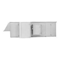
YORK SOLUTION LD09688
Johnson Controls YORK SOLUTION LD09688 Manuals
Manuals and User Guides for Johnson Controls YORK SOLUTION LD09688. We have
1
Johnson Controls YORK SOLUTION LD09688 manual available for free PDF download: Installation And Start-Up Instructions Manual
Johnson Controls YORK SOLUTION LD09688 Installation And Start-Up Instructions Manual (140 pages)
Brand:
Johnson Controls
| Category:
Air Handlers
| Size: 7 MB
Table of Contents
General Safety Guidelines
2
Changeability of this Document
3
Table of Contents
5
Table of Contents
6
List of Figures
11
Introduction
17
General
17
Typical YORK Solution Operation in "Hvac" System
17
Fig. 1 - Cutaway of YORK Solution Showing Various Segments
17
Ventilation System
17
Cooling Operation
18
Economizer System - Typical
18
Heating Operation
18
Hand Identification
18
Fig. 2 - Unit and Coil Hand Identification
18
Segment Identification
19
Table 1 - Segment Identification
19
Table 2 - Unit Nomenclature
20
Unit Identification
21
Fig. 3 - Unit ID Label
21
Fig. 4 - Skid ID Label
21
Fig. 5 - Segment ID Box Example
21
Segment Identification Box
21
Skid ID Label
21
Unit ID Label
21
Filter ID Label
22
Loose Component ID Label
22
Direction of Airflow
22
Fig. 6 - Loose Component ID Labels
22
Fig. 7 - Filter Labels
22
1 0 PRE-Installation
23
Receiving
23
Rigging of Indoor and Outdoor Units
23
Fig. 1-1 - Recommended Lifting with Four Lifting Points
23
Fig. 1-2 - Recommended Lifting with Multiple Points
23
Come-A-Longs or Power Pull
24
Crane and Spreader Bars
24
Fig. 1-3 - Typical COME-A-Long Types
24
Fork Lift
24
Off-Loading
24
Table 1-1 - Spacing Requirements for Offloading Long Units
24
Fig. 1-4 - PROPER Lifting with Shackle at Corner
25
Fig. 1-5 - PROPER Lifting with Shackle at Lifting Lug
25
Fig. 1-6 - Recommended Lifting with Baserail
25
Shackles
25
Inspection
26
Check for Damage
26
Indoor Units
26
Outdoor Units
26
Receiver Responsibility
26
Checking for Non Mounted Parts
26
Storage
26
Short-Term Storage
26
Long-Term Storage
27
Periodic Fan Check
27
Preventive Maintenance Prior to Long Term Storage
27
Fig. 1-7 - Long-Term Storage Requirement - Field Preparation
28
Fig. 1-8 - Long-Term Storage Periodic Checklist and Logs
29
2 0 Installation
31
Site Preparation
31
Outdoor Units (Site Prep)
31
Fig. 2-1 - Minimum Service Clearances
31
Curb
32
Mounting
32
Steel Frame
33
Indoor Units (Site Prep)
33
Fig. 2-2 - Typical Curb Assembly
34
Clearance
35
Mounting
35
Fig. 2-3 - no Baserail - Housekeeping Pad Required to Accommodate Trap Height
35
Fig. 2-4 - no Housekeeping Pad - Baserail Required to Accommodate Trap Height
35
Fig. 2-5 - with Baserail and Housekeeping Pad
35
Floor
35
Housekeeping Pad
35
Ceiling Suspended Units
36
Fig. 2-6 - Ceiling Suspended Unit
36
Unit Installation
37
Tools Needed
37
Fig. 2-7 - Tools Typically Used for Assembly of Shipping Splits
37
Ship Loose Parts
38
Fig. 2-8 - Second Tier Tie-Down Fastener PACK P/N 386-03419-000
38
Fig. 2-9 - Bottom RACEWAY Shipping Split Fastener Packp/N 386-03418-000
38
Fig. 2-10 - Baserail Shipping Split Fastener PACK P/N 386-03417-000
38
Fig. 2-11 - Top RACEWAY Split Fastener PACK
38
Fig. 2-12 - Pipe Chase, Hoods & SEAM CAPS
39
Fig. 2-13 - Miscellaneous Parts for Options
40
Fig. 2-14 - Hardware, Gasketing, Caulk, Paint and Tape
41
Fig. 2-15 - SHIPPING SPLIT EXAMPLES
42
Fig. 2-16 - SHIPPING SPLIT EXAMPLES for EXPANDED CABINET
42
Assembly of Outdoor Unit
43
Installing Single Piece Outdoor Unit
43
Installing Multiple Piece Outdoor Unit
43
Fig. 2-17 - Applying Gasket
44
Fig. 2-18 - Electrical Connections
44
Fig. 2-19 - REMOVE and Reposition Shipping Split Angle
45
Fig. 2-20 - Bringing Sections Together
46
Assembly of Indoor Unit
47
Installing Multiple Piece Indoor Unit
47
Fig. 2-21 - Applying Gasket to Shippingsplit
47
Fig. 2-22 - Applying Gasket to Door Framewhen at Shipping Split
47
Fig. 2-23 - Assembly of End Channel Shipping Split (Expanded Cabinet)
48
Fig. 2-24 - REMOVE and Reposition Shipping Split Angle
48
Fig. 2-25 - Placing and Anchoring First Section and Attaching COME-A-Longs
49
Fig. 2-26 - REMOVE Lifting Lugs and SAVE Hardware
49
Fig. 2-27 - Electrical Connections
49
Fig. 2-28 - Installing Bolts after Pulling Units Tight Together
50
Installation of Tiered Unit
51
Fig. 2-29 - Tiered Unit
51
Fig. 2-30 - Tiered Unit Secured with Brackets
51
Fig. 2-31 - Apply Gaskets to Top Panel Bottom Tier
51
Fig. 2-32 - Guiding Brackets Together
52
Assembly of End Channel Shipping Split
53
Fig. 2-33 - Assembly of End Channel Shipping Split
53
Hood Installation with Optional Mist Eliminators
54
Outdoor Air Temperature And/Or Humidity Sensors
54
Fig. 2-34 - Hood Installation with Optional Mist Eliminators
54
Actuator Installation
55
Fig. 2-35 - Direct Coupled on Jackshaft
55
Installation of Multizone (MZ) Dampers
56
Damper Installation
56
Fig. 2-36 - MZ Damper/Actuator Assembly
56
Actuator Installation Mutlizone (MZ) - Field Supplied
57
Inertia Fan BASE Fill Instruction
57
Humidifiers
57
Fig. 2-37 - DAMPER SHAFT EXTENSION KIT
57
Uvc Emitter Lights
58
Fig. 2-38 - V-Mod Installation
58
Fig. 2-39 - V-RAY Installation
58
Fig. 2-40 - V-FLEX INSTALLATION
58
Air Measuring Device Connections (When Provided)
59
Air Measuring at the Fan Inlets
59
Air Measuring at Unit Inlets
59
Pipe Chase Installation
60
Tools Required
60
Materials Required
60
Procedure
60
Fig. 2-41 - Install Gasket under ROOF Overhang
60
Fig. 2-42 - Apply Gasket to Pipe Chase
61
Fig. 2-43 - Pipe Chase Baserail to Unit Baserail Installation
61
Fig. 2-44 - SCREW Pipe Chase Top and Bottom Internal Flanges to Air Handler
61
Fig. 2-45 - Baserail Caulk Application
62
Fig. 2-46 - Pipe Chase to ROOF Installation
62
Fig. 2-47 - Pipe Chase to Air Handler Caulk Application
62
Fig. 2-48 - Install COVER Angle
62
Fig. 2-49 - PROPER Positioning of COVER Angle with Notch on Air Handler Side
63
Fig. 2-50 - PROPER Pattern for Installing Self-Drilling SCREWS to
63
Fig. 2-51 - Baserail COVER Application
63
Condensate Drain Arrangement
65
Fig. 2-53 - Gas Furnace Condensate Drain Trap
65
Electrical - General
66
POWER Connections
67
Single Point Power
67
Motors for Supply Fan, Return Fan, Exhaust Fan
67
Energy Recovery Wheel Option
67
Fig. 2-54 - Typical Motor Data / Nameplate
67
Fig. 2-55 - Typical POWER Wiring of Energy RECOVERY Wheel
67
Gas Heat Option
68
Fig. 2-56 - Gas Burner Component Locations
68
Electric Heat Option
69
Available Power Options
69
Electric Heat Disconnect Switch Options
69
Fig. 2-58 - Typical Electric Heat Control Panel Interior Wiring and
69
Fig. 2-59 - Typical Field Control and POWER Connections
69
Available Control Options
70
Installation
70
Application Information
70
Mechanical Installation
70
Fig. 2-60 - Pressure PROBE Direction
71
Fig. 2-61 - Airflow Switch Connections
71
Electrical Installation
72
Humidifier Option (Electric)
73
Humidifier Option
73
Fig. 2-62 - Typical Humidifier Panel Layout
73
Fig. 2-63 - Supply POWER Knockouts
73
Fig. 2-64 - Humidifier Points
73
Piping Connections
74
Fig. 2-65 - Pipe Chase Enclosure
74
Fig. 2-66 - Factory Coil Connections
74
Coil Piping
75
Staggered Coils
75
Fig. 2-67 - Staggered Coil Configurations
75
Fig. 2-68 - Chilled Water Coil Connections
76
Hot and Chilled Water Coil Performance
76
Water
76
Water Coils - Hot Water and Chilled Water
76
Fig. 2-69 - Hot Water Piping - 2 WAY Valve
77
Fig. 2-70 - Hot Water Piping with Diverting Valve
77
Steam
78
Steam Coils
78
Steam Control
78
Steam Distributing Coils
78
Water Treatment
78
Fig. 2-71 - Steam Coil Piping Arrangements
79
Steam Traps
79
Fig. 2-72 - Integral FACE and BYPASS Coil (Horizontal; Tubes, Steam Shown)
80
Fig. 2-73 - Vertical Integral FACE and BYPASS Coil
80
Vifb and Ifb
80
Fig. 2-74 - Hot Water Piping for 2 ROW Coil Vifb
82
Fig. 2-75 - Hot Water Piping for Ifb
82
Fig. 2-76 - Steam Piping for Vifb Coil
83
Direct Expansion Coils (DX)
84
Fig. 2-77 - Typical Piping and Sundries at the DX Coil
84
Refrigeration
84
Combined Coil Types
85
DX Coil Circuiting
85
DX Coil Types
85
Fig. 2-78 - DX Coil Circuiting Types
85
Fig. 2-79 - Non-Stacked Coil Design - SQ Special
86
Fig. 2-80 - Non-Stacked Coil Design - Standard
86
DX Coil Circuiting and Staging
87
Fig. 2-81 - Stacked Coil Design - Standard
87
Fig. 2-82 - Stacked Coil Designs - SQ Special
87
Fig. 2-83 - Stacked Coil Circuiting
87
Fig. 2-84 - One Coil Circuit Perrefrigerant Circuit
88
Fig. 2-85 - Two Coil Circuits Perrefrigerant Circuit
88
Fig. 2-86 - Do Not Use the above Configuration
88
Fig. 2-87 - Three COMPRESSOR Ycul
88
Fig. 2-88 - Do Not Use the above Configuration
88
Fig. 2-89 - Six Compressor Ycul
89
Hot Gas Bypass
89
Maintaining Adequate Airflow
89
Thermostatic Expansion Valves (TXV)
89
VAV Systems
89
Condensate Drain Piping
91
Condensate Drain Trap
91
Fig. 2-90 - Drain Trap Showing Water Location During Draw through
91
Fig. 2-91 - Trap Detail for Draw through Application
91
Fig. 2-92 - Trap Detail for Blow through Application
91
Elevating Unit for Gravity Floor Drain Connections
92
Duct Connections
92
Duct Connection Guidelines
92
Fig. 2-93 - Combining Drain Lines
92
Fig. 2-94 - Recommended Discharge Duct Arrangement When Turns
92
Duct Connections
93
Fig. 2-95 - Recommended Discharge Duct Arrangement When Turns
93
Flanged Ducts or Sleeves
93
Raw or Straight Edge Ducts or Sleeves
93
Sound and Vibration Transmission
94
Front and Rear Discharge Outdoor Unit Duct Installation
94
Fig. 2-96 - Duct Penetration of ROOF
94
Fig. 2-97 - ROOF to Duct Installation - Horizontal Discharge
94
Air Filters
95
Filter Types
95
Maintenance and Replacement
95
Fig. 2-97A - Typical Filters
95
Filter Latches
96
Fig. 2-98 - Filter Latches
96
Installation of 2" Perfectpleat, Premium or Premium Hm
98
Fig. 2-100 - Fully Installed Filter
98
Fig. 2-99 - Correctly Installed Latch P/N 026-35778-000
98
Fig. 2-101 - Correctly Installed Latch P/N 026-35778-007
99
Fig. 2-102 - Place the End of the Latch over the Filter FRAME, Securing the Filter to the FRAME
99
Installation of 4" Amair 300X Pleated Filter
99
Installation of Spring Latches
99
Installation of Sh Single Headered Filters
100
Installation of Latches
100
Installation of a 2" Prefilter in Combination with a Single Header Final Filter
100
Fig. 2-103 - Installed Cartridge Filter
100
Fig. 2-104 - Install Latch P//N 026-35778-007
100
Fig. 2-105 - Installed Cartrige W/Pleats
100
Installation of a Varicel Dh Double Headered Filter
101
Installation of Spring Latches
101
Fig. 2-106 - Correct Use of Knockouts
101
Fig. 2-107 - Correct Latch/Knockout Configuration
101
Fig. 2-108 - FRAME with 4 Latches Installed
101
Fig. 2-109 - Spring Latch Should be Pulled and Fastened in Hole in the Header of the Filter
101
Installation of a 2" and 4" Prefilter in Combination with a Double Header Final Filter
102
Installation of Spring Latches
102
Installation of Prefilter Latches
102
Fig. 2-110 - Correct Latch/Knockout Configuration. P/N 026-35778-006
102
Fig. 2-111 - FRAME with 4 Latches Installed
102
Fig. 2-112 - Prefilter Latch after Installation Onto Filter Header
102
Fig. 2-113 - Position Prefilter in Front of the Final Filter
103
Fig. 2-114 - Spring the End of the Latch so that It Fits over the Edge of
103
Fig. 2-115 - Completed Assembly
103
Hepa Filters
104
Welded Bevel Seal Frame
104
Visual Control Filter Clamps
104
Fig. 2-116 - Hepa Filter FRAME CROSS Section View
104
Fig. 2-117 - Visual Control Filter Clamps
104
Fig. 2-118 - Hepa Filter Installation
105
Fig. 2-119 - Welded Bevel Seal Filter Installation
105
3 0 Startup
107
PRE Start-Up
108
Fig. 3-1 - Termination Chart Inside Enclosure Door
108
PRE Start up Fan Assembly Inspection
109
Motors - Odp Vs. Tefc
109
Fig. 3-2 - Fan and Motor Isolator Support FRAME
109
Fig. 3-3 - Odp (Open Drip PROOF)
109
Table 3-1 - Torque for Tightening Setscrews
109
Isolators
110
Fig. 3-4 - Tefc (Totally Enclosed Fan Cooled)
110
Fig. 3-5 - Spring Isolator
110
Fig. 3-6 - Seismic Snubber
110
Preparing Fan Isolators for Operation
110
Start-Up
111
Check Operation of Fans
111
Check Operation of Dampers
111
Airflow Control Dampers
111
Basic Actuators Installation
112
Damper Blade Orientation
112
Typical Actuators Locations
112
Energize Fan Motor(S)
113
Variable Speed Drive (Vsd)
113
Fig. 3-7 - Example of Sweep Balance Results
113
Set up of a Non-Factory Mounted Vfd
113
Check Doors and Latches for Proper Adjustment
114
Sheaves
114
Fig. 3-8 - Typical Drive Kit Data Tag
114
General Guidelines for Replacing an Adjustable Sheave with a Fixed Sheave
114
Energy Recovery Wheel
115
Fig. 3-10 - Outdoor Unit - Horizontal Wheel
115
Fig. 3-9 - Indoor Unit - Vertical Wheel
115
Indoor Units
115
Outdoor Units
115
Start-Up Procedure for Energy Recovery Wheel
115
Unit Configuration
115
Fig. 3-11 - Energy RECOVERY Wheel - Pulley Side
116
Fig. 3-12 - Segment Retainer
116
Fig. 3-13 - Diameter Seal Adjustment
116
Indirect Fired Gas Heat Start up
117
Identify the Unit Type
117
Introduction
117
Air Handler Pre Start Checks
118
Burner Pre Start Checks
118
Fig. 3-14 - Open Fuse Disconnects
118
Preliminary Coordination
118
Tools Recommended
118
Fig. 3-15 - Set ID Fan Damper
119
Fig. 3-16 - Check Main Gas Supply Pressure
119
Burner Start-Up Procedure
120
Fig. 3-17 - Draft over Fire Test Port
120
Fig. 3-18 - Flue (Stack) Combustion Temperature and Efficiency Test Port
120
Condensate Drain Arrangement
121
Fig. 3-19 - Damper Actuator
121
Fig. 3-21 - Gas Furnace Condensate Drain Trap
122
Table 3-3 - Pipe Size Required
125
Fig. 3-24 - Typical Wiring Diagram
128
Table 3-4 - Burner Teperature Rise
129
Electric Heat Startup
131
Airflow Requirements
131
Fig. 3-25 - Minimum Air Velocity Required for SAFE Operation
131
Fig. 3-26 - Pressure PROBE Direction
132
Fig. 3-27 - Airflow Switch Connections
132
Fig. 3-28 - Air Handler Start-Up Checklist
133
Table 3-5 - Inspection Requirements
134
Advertisement
Advertisement
Related Products
Johnson Controls YORK SOLUTION LD09624
Johnson Controls YORK EASYTANK LD17584
Johnson Controls YORK LD17583
Johnson Controls YORK LD17583RSR-1100V
Johnson Controls LD18545
Johnson Controls LD18546
Johnson Controls LHJD Series
Johnson Controls LSWU025
Johnson Controls LB-FMS1655-T04
Johnson Controls LN-UVL-1
Johnson Controls Categories
Controller
Air Conditioner
Thermostat
Control Unit
Irrigation System
More Johnson Controls Manuals
Login
Sign In
OR
Sign in with Facebook
Sign in with Google
Upload manual
Upload from disk
Upload from URL