
Subscribe to Our Youtube Channel
Related Manuals for P&B MPC2000+

Summary of Contents for P&B MPC2000+
- Page 1 MPC2000+ Technical Manual MPC2000+ Motor Protection Controller P&B Engineering Belle Vue Works Boundary Street Manchester M12 5NG Tel: 0161 230 6363 Fax: 0161 230 6464 E-mail mail@pbeng.co.uk ISSUE 7 28/9/99...
- Page 2 MPC2000+ Technical Manual Contents CONTENTS................................... 2 1. INTRODUCTION..............................1 2. SUMMARY OF MPC2000+ FEATURES ......................2 2.1. C ............................... 2 ONTROL UNCTIONS 2.2. P ............................2 ROTECTIVE UNCTIONS 2.3. D ..............................2 ISPLAYED 2.4. F ................................. 3 EATURES 3. TECHNICAL SPECIFICATION ..........................3 3.1.
-
Page 3: Table Of Contents
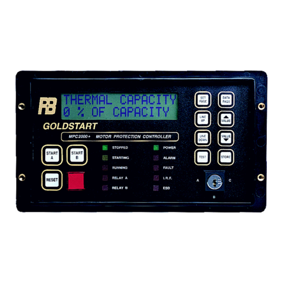
MPC2000+ Technical Manual 6.2.21. Emergency Stop (54) .............................10 7. MPC2000+ FACEPLATE FUNCTIONS ......................11 7.1. LED S ..............................11 TATUS ANEL 8. MPC FUNCTIONAL KEYPAD & DISPLAY ......................12 ..............................12 IQUID RYSTAL ISPLAY 9. MPC2000+ SETTING PAGES ..........................15 9.1. MPC2000+ C .........................15 OMMUNICATION ETTINGS 9.2. - Page 5 MPC2000+ Technical Manual 1. Introduction The MPC2000+ Goldstart Motor Protection Controller is a highly sophisticated microprocessor based motor protection and control unit, specifically designed to be used on motors with full load currents upto 2000 Amps, at any voltage and as an integral part of any type or manufacture of Motor Control Centre. All of the latest features are included in the MPC2000+ to allow total control, protection and monitoring of motor starters either by direct hard wire inputs or via the RS485 serial port.
- Page 6 MPC2000+ Technical Manual 2. Summary of MPC2000+ Features 2.1. Control Functions Full Control of: Direct on Line Motor Starters Direct on line Reversing Motor Starters Direct on Line 2 Speed Motor Starters Star/Delta Motor Starters Undervoltage Dip Restart Facility Motor Starts Limitation Integral Start &...
- Page 7 MPC2000+ Technical Manual Logic Inputs Status Motor Available Indication Individual Status of all Input Contacts Statistical Data Motor Hours Run Number of Motor Starts Last Start Time Last Peak Starting Current No of Motor Trips Fault Data Last Fault Last Alarm Phase Currents at Time of Trip Earth Fault Current at Time to Trip Phase Volts at Time of Trip...
- Page 8 MPC2000+ Technical Manual 3.3. Earth Fault Current Inputs Method: True RMS, sample time 0.5mS Range: 0.05 to 1.0 x E/F CT Primary Full Scale: 1.0 x E/F CT Primary Amps Setting Accuracy: +/- 1.5% of Full Scale 3.4. Line Voltage Inputs Method: True RMS, sample time 0.5mS Without VT Transformer...
- Page 9 MPC2000+ Technical Manual 3.8. Fault Time Delays Accuracy: +/- 0.5 seconds or +/- 2% of time Exceptions High Set Over-current: -0.1 to +0.2 sec. up to 1 second Earth Fault Trip: -0.1 to +0.2 sec. for less than 1 second delay Total Run Time Accuracy: +/- 2% 3.9.
- Page 10 MPC2000+ Technical Manual NOTE: CONTACTS SHOWN IN DE-ENERGISED STATE FOR OUTPUT RELAYS MPC2000+ WIRING DIAGRAM NOTE: TERMINAL 2 MUST BE CONNECTED TO THE EARTH STUD TERMINAL 7 NOTE: INTERNAL STAYPUT STOP SHOWN CONNECTED INTO MPC2000+ STOP INPUT PT100 THERMISTOR EXTERNAL FAULT 2 INTERNAL 2 POSITION SWITCH SHOWN CONNECTED [0.1K-30K] [100-240 OHMS]...
- Page 11 MPC2000+ Technical Manual 5. MPC2000+ Measured Inputs 5.1. Power Supply (Live-4, Neutral-5, Earth-7) The MPC2000+ requires 240 or 110v A.C. to supply the unit and provides the selected A.C. voltage to all external inputs. The voltage used is set via a switch situated on the rear cover of the unit. The MPC2000+ monitors the power supply assumed to be derived from the primary side of the contactor within the starter cubicle or from the MCC busbars to provide an Undervoltage Dip Restart facility.
- Page 12 MPC2000+ Technical Manual 6. MPC2000+ Control Inputs/Outputs 6.1. Output Relays The MPC2000+ has 4 output relays which can be assigned as follows: 32,33,34 - Contactor A = D.O.L., Forward, Star or High Speed 35,36 - Contactor B = Reverse, Delta or Low Speed 40,41,42 - Aux.
- Page 13 MPC2000+ Technical Manual 6.2.7. Plant Interlock (75) This contact represents the fulfilment of all plant conditions and needs to be closed before a start signal can be sent. Should these conditions change while the contactor is energised and the Plant Interlock opens then the output contactor will be de-energised and the MPC2000+ will inhibit starting until the plant interlock has been reset.
-
Page 14: Emergency Stop (54)
MPC2000+ Technical Manual 6.2.17. Isolator (56,57) This input enables the MPC2000+ to determine if the motor starter is in the isolated or service (available) position. With the N/O input open and the N/C input closed the motor starter is isolated and cannot be started. A changeover of both these contacts indicate the motor is in the service position and can be started. -
Page 15: Mpc2000+ Faceplate Functions
MPC2000+ Technical Manual 7. MPC2000+ Faceplate Functions The MPC2000+ Faceplate has been designed to provide all of the required information to the operator for the drive for which the unit is being used. This is achieved by using a LED Status Panel and a Functional Keypad with a LCD display. This eliminates the need for additional indication devices on the front of the motor starter panel such as Lamps, Ammeter, Voltmeter, Hours Run Indicator, Operations Counter, etc. -
Page 16: Mpc Functional Keypad & Display
MPC2000+ Technical Manual RELAY B This red LED illuminates when Contactor B is closed, indicating that the Delta, Reverse or High speed contactors are closed. ALARM This red LED indicates that one of the MPC2000+ Alarm functions has operated and remains lit until the condition no longer exists and a reset has been performed. - Page 17 MPC2000+ Technical Manual DATA PAGE This key when pressed enables the operator to select a page of MPC2000+ Displayable Data. For convenience the data are grouped into logical pages. Each time the key titles as follows: Measured Data Calculated Data Logical Inputs - Contacts Status Statistical Data Fault Data...
- Page 18 MPC2000+ Technical Manual Note: It is possible to adjust and store setting parameters at any time , even whilst the motor is running. Changing the value of a displayed parameter has no effect on the operation of the units until the STORE key is pressed. After setting parameters have been stored to the EEPROM memory they are kept indefinitely, this feature does not rely on a battery backup system.
-
Page 19: Mpc2000+ Setting
MPC2000+ Technical Manual 9. MPC2000+ Setting Pages 9.1. MPC2000+ Communication Settings Drive Number This setting range 0-320 with a default setting of 0, identifies the MPC2000+ by an overall system number . This does not affect the communications which uses the Serial Link Number. Baud Rate This setting range 110, 300, 1200, 4800, 9600, 19200 Bits/Second with a default setting of 9600, determines the speed of communications between the PCX or when directly connected the Host system and the MPC2000+. - Page 20 MPC2000+ Technical Manual Earth Fault Alarm This setting range 1-100% FLC in steps of 1%, with a default setting of 5% specifies the level of earth fault current before an alarm occurs. Earth Fault Alarm Delay This setting is used to select the time between an earth fault being registered and an alarm signal being activated. Range 1-60 seconds in steps of 1s with a default setting of 10s.
- Page 21 MPC2000+ Technical Manual Designate Aux. 2 This setting, range Trip, Trip-Fail Safe, Slave to Contactor A or Slave to Contactor B output, with a default setting of 'Trip' determines the use of the Aux 2 relay. Aux.2 Delay This setting range 0-120s in steps of 1s, with a default setting of 0, allows the user to set a time delay on the operation of the Aux.2 relay.
-
Page 22: Voltage Settings
MPC2000+ Technical Manual 9.3. Voltage Settings Undervoltage Setting This setting range 50-95% in steps of 1% with default setting of 80% of line voltage determines the pick up level of the Undervoltage protection. When the measured voltages reaches this level for the period equal to the Undervoltage Delay period a trip will be performed, unless the Undervoltage Restart feature is selected. - Page 23 MPC2000+ Technical Manual Undercurrent Alarm If the current falls the MPC2000+ will sense this and an alarm will be signalled at a set percentage of FLC. This setting has a range 10 - 90% in steps of 1% of FLC, with a default setting of 50%. Undercurrent Alarm Delay Linked to the undercurrent alarm this function can be pre-set to determine how long an undercurrent below the setting can occur before an alarm will be signalled.
- Page 24 MPC2000+ Technical Manual Hot/Cold Ratio Adjustable between 20 and 100% in steps of 1%, with a default setting of 50%. For further information refer to section 'MPC2000+ Thermal Overload Protection' Cool Time Factor This setting specifies the time factor at which the running motor will cool down once it has been stopped. Adjustable between the range of 1 to 15 in steps of 1 times the heating constant with a default setting of 5.
- Page 25 MPC2000+ Technical Manual Current Unbalance Time Constant This setting determines the time that the current may be unbalanced before a trip is initiated. The setting is adjustable via the keypad. The value To has the range 20 - 120 seconds in steps of 1 second, the default value being 30 seconds, and it refers to the inverse slope of the time verses %unbalance characteristic which has a reference point corresponding to an Unbalance of 10%.
-
Page 26: Temperature Settings
MPC2000+ Technical Manual 9.5. Temperature Settings RTD/Thermistor This setting range: 'RTD' or 'Thermistor', with a default setting of 'RTD', determines whether Resistance Temperature Detectors or Thermistors are being used for temperature monitoring. In addition to this setting a change in the setting of an internal group of dip switches is required, refer to notes given in the MPC Measured Inputs section. - Page 27 MPC2000+ Technical Manual This page contains the following settings for each protective function incorporated in the MPC2000+. Trip This setting range 'Enable' or 'Disable' determines whether operation of the protective function causes a trip to the motor or not. This can be applied to an alarm such that an alarm can be made to give a trip. Alarm The option, 'Enable' or 'Disable' determines whether the protective functions cause an alarm to occur and is applicable to both alarm and trip protective functions.
- Page 28 MPC2000+ Technical Manual The following list details all of the MPC2000+ protective functions for which the above settings are included. On the right hand side of the page is the default setting, E=Enabled and D=Disabled. T=Trip A=Alarm AR=Auto-Reset PR=Panel Reset R=Remote Reset The above options are provided individually for all of the following MPC2000+ protective and control functions: Function...
-
Page 29: Mpc2000+ Data Display
MPC2000+ Technical Manual 9.7. MPC2000+ Data Display Pages The following menus can be displayed by the Data Page Key: Measured Data Calculated Data Logical Inputs/Contact Status Statistical Data Fault Data Each data page provides the following displayed information: Measured Data Phase and Line Voltages (+/- 1.0%) Phase Currents... -
Page 30: Mpc2000+ Setting Pages Summary
MPC2000+ Technical Manual 9.8. MPC2000+ Setting Pages Summary COMMUNICATION SETTINGS Drive Number 1 - 320 Baud Rate 110,300,1200,2400,4800,9600,19200 9600 Serial Link No. 1 - 33 Fast Scan Anal 1 0 - 201 Fast Scan Anal 2 0 - 201 Fast Scan Anal 3 0 - 201 Fast Scan Update 0-30s... - Page 31 MPC2000+ Technical Manual TEMPERATURE SETTINGS CH 1 2 3 Sensor RTD/Thermistor Thermistor Type PTC,NTC Channel 1 Alarm 100-240 or 100-30,000 ohm 100 ohm Channel 2 Alarm 100-240 or 100-30,000 ohm 100 ohm Channel 3 Alarm 100-240 or 100-30,000 ohm 100 ohm Channel 1 Trip 100-240 or 100-30,000 ohm 100 ohm...
-
Page 32: Mpc2000+ Data Pages Summary
MPC2000+ Technical Manual 9.9. MPC2000+ Data Pages Summary MEASURED DATA VP1, VP2, VP3 Volts VL1, VL2, VL3 Volts I1, I2, I3 Amps E/F Current Amps Total Real Power Watts Total Va Power Power Factor R1, R2, R3 Ohms CALCULATED DATA Motor Load Thermal Capacity Time to Trip... -
Page 33: Mpc2000+ Communications
MPC2000+ Technical Manual 10. MPC2000+ Communications The Intelligent Motor Protection and Control system offered utilises our very latest development the MPC2000+ Motor Protection and Controller. The MPC2000+ in addition to its very comprehensive protection and control features has been equipped with a very powerful data communications system. -
Page 34: Mpc2000+ Internal Test Routines
MPC2000+ Technical Manual SELF TEST FAILED ERROR CODE 32 This Flash message is displayed if an error has been found during the operation of the 'Run Self Test' function in the Test/Maintenance Options. HARD WIRED START This message is displayed constantly after the MPC2000+ has recognised a Hard Wired Start, this is defined as a motor start which is not the result of an MPC2000+ command. -
Page 35: Mpc2000+ Fault Finding
MPC2000+ Technical Manual 13. MPC2000+ Fault Finding This procedure details some of the more common faults which may cause the MPC2000+ to not operate as required. This is usually due to incorrect settings or logic and will hopefully assist to rectify the situation. •Check all connections at the rear of the unit have been made correctly, especially:- Interlock Isolator... -
Page 36: Mpc2000+ Thermal Overload Protection
MPC2000+ Technical Manual 14. MPC2000+ Thermal Overload Protection MPC2000+ Thermal Operating Curves The curves shown are the time/current operating characteristics for the MPC2000+ Thermal Overload protection. Curve 1 :Cold Curve Overload Setting =105% Curve 2 :Hot Curve Overload Setting =105% Running From 100% FLC Hot/Cold Ratio = 80% Curve 3 : Hot Curve... - Page 37 MPC2000+ Technical Manual When the running current exceeds the overload setting the thermal capacity will eventually reach 100% and trip the motor. The time taken depends on the present value of thermal capacity used and the t6x setting, which is set as the time to trip for a motor in a cold condition when the current is at 6 times the motor rated FLC.
- Page 38 MPC2000+ Technical Manual Example Application As an example of applying the MPC2000+ Thermal Overload protection to a motor let us establish the settings for a particular motor having the following characteristics: Rating: 100Kw Start Time 8 sec @ 6xFLC System Volts 415 Volts Cold Withstand 22 Seconds...
- Page 39 MPC2000+ Technical Manual p 2 - (1-H/C)(I L ) 2 t c = 32.a.log e -------------------- p 2 - s 2 Where 'I L' is the steady state load prior to overload condition divided by motor FLC, e.g. if motor is running at FLC, I L =1.
-
Page 40: Mpc2000+ Installation
MPC2000+ Technical Manual 15. MPC2000+ Installation 15.1. Casing The MPC2000+ is supplied in a totally metal enclosed case suitable for flush mounting on the front of the motor starter cubicle. The following dimensional drawing for the MPC2000+ shows the standard flush mounted unit. 211.5 13.5 125.0... -
Page 41: Mpc2000+ Terminations
MPC2000+ Technical Manual 15.2 MPC2000+ Terminations All terminations to the MPC2000+ are situated on the rear plate of the unit. All external connections are made using Phoenix clamp type terminals grouped in plug in sections to allow pre-wiring to be carried out prior to fitting into the motor starter cubicle. These are suitable for accepting 1sq mm wire. The following diagram shows the position of the terminals as viewed from the rear of the MPC2000+. - Page 42 MPC2000+ Technical Manual CONNECTOR 2, 4 WAY, AUX. SUPPLY. PIN NUMBER. SIGNAL. TERMINAL NUMBER. AUX. SUPPLY LIVE. AUX SUPPLY NEUTRAL. NO CONNECTION. AUX. SUPPLY EARTH. CONNECTOR 3, 8 WAY, CURRENT INPUTS. PIN NUMBER. SIGNAL. TERMINAL NUMBER. CT0+ CT0- CT1+ CT1- CT2+ CT2- CT3+...
- Page 43 MPC2000+ Technical Manual CONNECTOR 5, 16 WAY, AUXILIARY RELAY CONTACTS. PIN NUMBER. SIGNAL. TERMINAL NUMBER. CONTACTOR A N/O CONTACTOR A C CONTACTOR A N/C CONTACTOR B N/O CONTACTOR B C AUX RELAY 2 N/O AUX RELAY 2 C AUX RELAY 2 N/C AUX RELAY 1 N/C AUX RELAY 1 C AUX RELAY 1 N/O...
- Page 44 MPC2000+ Technical Manual CONNECTOR 7, 16 WAY, DIGITAL INPUTS. PIN NUMBER. SIGNAL. TERMINAL NUMBER. SPEED SWITCH. AUX. LIVE. PLC CONTROL B. PLC CONTROL A. AUX. LIVE. PLC RESET. AUTHORISE KEY. AUX. LIVE. PLC \ SERIAL PORT. LOCAL \ REMOTE. AUX. LIVE. PLANT INTERLOCK.
-
Page 45: Starting Methods
MPC2000+ Technical Manual 16. Starting Methods. The MPC2000+ can control motors in a variety of different ways. The MPC2000+ can also control circuit breakers. This section details the different ways of controlling a motor and the new variables that need setting on the MPC2000+. -
Page 46: Fast Scan Analogue Data
MPC2000+ Technical Manual 17. Fast Scan Analogue Data The Fast Scan Analogue 1,2 and 3 can have the following data assigned to them to be read back to the PCX:- Address Data Represented. Address Data Represented. Current in I1 Hardwire Command Current in I2 Total run time Current in I3...
Need help?
Do you have a question about the MPC2000+ and is the answer not in the manual?
Questions and answers