Lenze 9350 Operating Instructions Manual
Hide thumbs
Also See for 9350:
- Operating instructions manual (55 pages) ,
- Operating instructions manual (146 pages)
Table of Contents
Advertisement
Quick Links
Advertisement
Table of Contents

Related Manuals for Lenze 9350


Summary of Contents for Lenze 9350
- Page 1 Show/Hide Bookmarks EDB9350UE 00394036 Operating Instructions 9350 brake unit...
- Page 2 Show/Hide Bookmarks These Operating Instructions are valid for brake units with the following nameplate data: 33. 935X- E. 1x (9351 - 9352) 33. 935X- E. 1x V003 Cold plate (9351 - 9352) In connection with the unit series as from the nameplate data: 33.
- Page 3 Show/Hide Bookmarks Pos. Name/ Note Meaning Brake unit 9351-E brake module 9352-E brake chopper Connections Voltage link: + U , -U only 9351-E brake module: Thermostat: T1, T2 only 9352-E brake chopper: Brake resistor: RB1, RB2 (T1) (T2) Display of the operating state green: - on, when voltage is applied to terminals + U...
- Page 4 Show/Hide Bookmarks Safety and application notes for controllers (according to: Low-Voltage Directive 73/23/EEC) 1. General During operation, drive controllers may have, according to their type of protec- tion, live, bare, in some cases also movable or rotating parts as well as hot sur- faces.
- Page 5 Show/Hide Bookmarks 4. Erection The devices must erected and cooled according to the regulations of the cor- responding documentation. The drive controllers must be protected from inappropriate loads. Particularly during transport and handling, components must not be bent and/or isolating distances must not be changed.
-
Page 6: Table Of Contents
Show/Hide Bookmarks Contents 1 Preface and general information ... . 1.1 About these Operating Instructions ....1.1.1 Terminology used . - Page 7 Show/Hide Bookmarks Contents 4 Installation ....... . 4.1 Mechanical installation .
-
Page 8: About These Operating Instructions
In the following, the term ”controller” is used for ”93XX servo inverters” or ”82XX frequency inverters”. Drive system For drive systems with 935X brake units and other Lenze drive components, the term ”drive system” is used in the following text. 1.1.2 What is new? Material no. -
Page 9: Scope Of Delivery
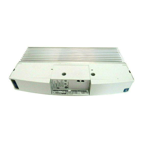
- visible deficiencies/incompleteness immediately to your Lenze representative. 1.3 9351 and 9352 brake units 1.3.1 Labelling - Lenze 935X brake units are clearly identified by the indications on the nameplate. - CE mark - Conformity with the EC Low-Voltage Directive - Manufacturer: - Lenze GmbH &... -
Page 10: Application As Directed
Preface and general information 1.3.2 Application as directed 935X brake units - Additional units for Lenze controllers: - 822X frequency inverters (8221 to 8227) - 824X frequency inverters (8241 to 8246) - 93XX servo inverters (9321 to 9333) - Operation with 820X or 821X frequency inverters is possible. -
Page 11: Legal Regulations
- Operating mistakes - Improper working on and with the brake units Warranty - Terms of warranty: see terms of sale and delivery of Lenze GmbH & Co KG. - Warranty claims must be made to Lenze immediately after detecting the deficiency or fault. -
Page 12: Ec Directives/Declaration Of Conformity
Show/Hide Bookmarks Preface and general information Disposal The brake unit consists of different materials. Please observe the current environmental directives for recycling or disposing of material: Material recycle dispose Metal Plastic Printed-board assemblies 1.4 EC Directives/Declaration of Conformity 1.4.1 What is the purpose of EC directives? EC directives are issued by the European Council and are intended for the determination of common technical requirements (harmonization) and certification procedures within the European... -
Page 13: Ec Low-Voltage Directive
Show/Hide Bookmarks Preface and general information 1.4.3 EC Low-Voltage Directive (73/23/EEC) amended by: CE Mark Directive (93/68/EEC) General - The Low-Voltage Directive is effective for all electrical equipment for use with a rated voltage between 50 V and 1000 V AC and between 75 and 1500 V DC and with normal ambient conditions. - Page 14 The 9351 brake modules and the 9352 brake choppers were developed, designed, and manufactured in compliance with the EC Directive stated above under the sole responsibility of Lenze GmbH & Co KG, Postfach 10 13 52, D-31763 Hameln Considered standards: Standard DIN VDE 0160 5.88 + A1 / 4.89 + A2 / 10.88...
-
Page 15: Ec Machinery Directive
Show/Hide Bookmarks Preface and general information 1.4.4 EC Machinery Directive (89/392/EEC) amended by: First Amendment Directive (91/368/EEC) Second Amendment Directive (93/44/EEC) CE Mark Directive (93/68/EEC) General For the purpose of the Machinery Directive, ”machinery” means an assembly of linked parts or components, at least one of which moves, with the appropriate actuators, control and power circuits, etc., joined together for a specific application, in particular for the processing, treatment, moving or packaging of a material. - Page 16 Lenze GmbH & Co KG, Postfach 10 13 52, D-31763 Hameln Commissioning of the 9351 brake modules and the 9352 brake choppers is prohibited until it is proven that the machine where they are to be installed corresponds to the EC Machinery Directive.
- Page 17 Show/Hide Bookmarks Preface and general information 1-10 9350BA0197...
-
Page 18: Safety Information
Show/Hide Bookmarks Safety information 2 Safety information 2.1 Personnel responsible for safety Operator - An operator is any natural or legal person who uses the drive system or on behalf of whom the drive system is used. - The operator or his safety officer are obliged - to check whether all relevant regulations, notes, and laws are observed. -
Page 19: General Safety Information
- Electrical or non-electrical protection (latching or mechanical blocking) - Measures covering the complete system - Only operate the drive system in a perfect condition. - Changes or retrofittings at the brake unit are prohibited in principle. In any case, Lenze must be contacted. 9350BA0197... -
Page 20: Layout Of The Safety Information
Show/Hide Bookmarks Safety information 2.3 Layout of the safety information - All safety information in these operating instructions has a uniform layout: Signal word Note - The icon designates the type of danger. - The signal word designates the severity of danger. - The note describes the danger and suggests how to avoid the danger. -
Page 21: Residual Hazards
Show/Hide Bookmarks Safety information 2.4 Residual hazards Operator’s safety - After mains voltage connection, the power terminals , -U and RB1, RB2 remain live for up to three minutes. - S1, S2 and S3 are live! - Wait for at least 3 minutes before you change the switch position. -
Page 22: Brake Units
Show/Hide Bookmarks Installation 4 Installation 4.1 Mechanical installation 4.1.1 Important notes - Use the brake units only as built-in devices! - Observe free space! - Allow a free space of 100 mm at the top and at the bottom. - Ensure unimpeded ventilation of cooling air and outlet of exhaust air. - Page 23 Show/Hide Bookmarks Installation Possible mounting positions - In vertical position on the back panel of the control cabinet, power connections at top - fixed with attached fixing rails (see chapter4.1.2) - thermal separation via external heat sink (”push-through technique”) (see chapter 4.1.3) - thermal separation via external convection cooler (”Cold plate”...
- Page 24 Show/Hide Bookmarks Installation 4.1.3 Assembly with thermally separated power stage (”Push-through technique”) The heat sinks of the brake units can also be externally mounted to reduce the heat generated in the control cabinet.You need an assembly frame with seal (see Accessories). - Distribution of the power loss: - approx.
- Page 25 Show/Hide Bookmarks Installation Fig. 4-2 935X dimensions: Assembly with thermally separated power stage [mm] 9351 / 9352 280 379 28 140 252 41 141 238 338 250 90 Assembly cut-out Z [mm] Height Width ± ± 9351 / 9352 9350BA0197...
- Page 26 Show/Hide Bookmarks Installation 4.1.4 Assembly of the 935X-V003 ”Cold plate” variant 4.1.4.1 General Fields of application This variant is used mainly for the following applications: - Application of cooling units without separately driven fan: - e.g. if the cooling air is so contaminated, that it is not possible to use separately driven fans, since the performance as well as the service life would be reduced.
- Page 27 Show/Hide Bookmarks Installation 4.1.4.2 Demands on the cooler Coolers, which can use different coolants (air, water, oil, etc.) can dissipate the power loss of the brake unit. In addition to the features required by the user, the following features are important for safe operation: - Good thermal connection to the cooler - The contact surface between the external cooler and the cold plate of the brake unit must be at least twice as...
- Page 28 Show/Hide Bookmarks Installation 4.1.4.3 Thermal performance of the whole system The thermal conditions of a system are influenced by several factors.Consider the following points for the right selection of the control cabinet for your system: Ambient temperature of the controller The rated data and the corresponding derating factors for higher temperatures are still valid for the ambient temperature of the brake unit.
- Page 29 Show/Hide Bookmarks Installation 4.1.4.4 Assembly of 935X-V003 - Apply the supplied heat-conducting paste before you bolt the cooler to the cold plate of the brake unit, to reduce the heat transfer resistance to its minimum. - The heat-conducting paste which you find in the accessory kit is enough for an area of approx.
- Page 30 Show/Hide Bookmarks Installation Fig. 4-3 935X-V003 assembly: Control-cabinet assembly [mm] 9351-V003 9352-V003 9350BA0197...
-
Page 31: Electrical Installation
Show/Hide Bookmarks Installation 4.2 Electrical installation 4.2.1 Operator’s safety Danger! - After mains voltage connection, the power terminals , -U and RB1, RB2 remain live for up to three minutes. - S1, S2 and S3 are live! - Wait for at least 3 minutes before you change the switch position. - Page 32 Show/Hide Bookmarks Installation 4.2.2 Protection of the brake unit Stop! The brake units contain electrostatically sensitive components. - Prior to assembly and service operations, the personnel must be free of electrostatic charge: - They can discharge themselves by touching the PE fixing screw or another grounded metal part in the control cabinet.
-
Page 33: Connection
- The compliance with other standards (e.g.: VDE 0113, VDE 0289, etc.) remains the responsibility of the user. 4.3.2 Permissible cable lengths For trouble-free operation of the 9350 brake units, please observe these installation instructions: Cable 9351 brake module 9352 brake chopper controller ⇔... - Page 34 Show/Hide Bookmarks Installation + U G - U G - U G 9 3 X X 8 2 2 X / 8 2 4 X £ 2 m £ 2 m Fig. 4-4 Diagram example for parallel operation 93XX Controller of the 9300 series 822X/824X Controller of the 8220 or 8240 series Brake chopper 1 = master...
-
Page 35: Fuses
Show/Hide Bookmarks Installation 4.3.3 Fuses - Fuses in UL-conform plant must have a UL approval. - The rated voltage of the fuses must be selected according to the DC-bus voltage. - The application of DC-bus fuses is a recommendation. - If you use DC-bus fuses, they must meet the specifications stated in chapter 3.3.3. - Page 36 Show/Hide Bookmarks Installation 4.3.4 Connection of temperature monitoring Danger! - Always connect temperature monitoring. - The temperature monitoring is required to ensure safe switch-off in the event of a failure. Connect the temperature switches of the external brake resistors or the 9351 brake module to the monitoring circuit so that, in the event of the activation of temperature monitoring - all controllers connected to the brake units of which the temperature monitoring has been activated, are...
- Page 37 Show/Hide Bookmarks Installation 4.3.5 9351 brake module at 822X controller Fig. 4-5 Connection of 9351 brake module to 822X controller Brake module Controller Mains choke Mains contactor F1 ... F3: Mains fuses F4, F5 DC-bus fuses (recommendation) Factory setting Mains voltage [V 400 ...
- Page 38 Show/Hide Bookmarks Installation 4.3.6 9352 brake chopper at 822X controller Fig. 4-6 Connection of 9352 brake chopper to 822X controller Z1 Brake chopper Controller Mains choke Brake resistor Mains contactor F1 ... F3: Mains fuses F4, F5 DC-bus fuses (recommendation) Factory setting Mains voltage [V 400 ...
- Page 39 Show/Hide Bookmarks Installation 4.3.7 9351 brake module to 93XX controller Fig. 4-7 Connection of 9351 brake module to 93XX controller Brake module Controller Mains choke Mains contactor F1 ... F3: Mains fuses F4, F5 DC-bus fuses (recommendation) Factory setting Mains voltage [V 400 ...
- Page 40 Show/Hide Bookmarks Installation 4.3.8 9352 brake chopper to 93XX controller Fig. 4-8 Connection of 9352 brake chopper to 93XX controller Brake chopper Controller Mains choke Brake resistor Mains contactor F1 ... F3: Mains fuses F4, F5 DC-bus fuses (recommendation) Factory setting Mains voltage [V 400 ...
- Page 41 Show/Hide Bookmarks Installation 4.3.9 Threshold adjustment Danger! - S1, S2 and S3 are live! - Wait for at least 3 minutes before you change the switch position. Important notes The threshold of the brake unit is the voltage in the DC bus at which the brake resistor is activated.
- Page 42 Show/Hide Bookmarks Installation Setting 1. Switch the controller free of potential and wait for 3 minutes until the capacitors of the DC-bus circuit are discharged. 2. Remove the terminal cover of the control terminals (above) from the brake unit. 3. Set the switches S1 and S2 according to the following table: Factory setting Mains voltage [V...
-
Page 43: Parallel Connection Of Brake Units
Show/Hide Bookmarks Installation 4.4 Parallel connection of brake units Danger! - S1, S2 and S3 are live! - Wait for at least 3 minutes before you change the switch position. The 935X brake units can be connected in any parallel connection if a single brake unit cannot completely convert the generated brake power. - Page 44 Show/Hide Bookmarks Installation Stop! Correct synchronization of brake units connected in parallel: - Set the threshold of all brake units to the same value (see chapter 4.3.9). - Correct connection of synchronization interfaces - Output: A1, A2 / Input E1, E2; (see fold-out page) - Total lengths of ≤...
- Page 45 Show/Hide Bookmarks Installation 4-24 9350BA0197...
- Page 46 Show/Hide Bookmarks Installation Fig. 4-9 Parallel connection of brake units, Example with 9352 Brake chopper 1 = Master (S3 = OFF) Brake chopper 2 = Slave (S3 = ON) Brake chopper x = Slave (S3 = ON) Mains choke Controller Z11, Z12, Z1x..: External brake resistors Mains contactor...
- Page 47 Show/Hide Bookmarks Installation 4-26 9350BA0197...
-
Page 48: Troubleshooting And Fault Elimination
Show/Hide Bookmarks Troubleshooting and fault elimination 6 Troubleshooting and fault elimination Fault Cause Remedy - Switch on the mains Green LED is not on No voltage at terminals + U , -U - Connect the brake unit to the ter- minals + U , -U of the controller... - Page 49 Show/Hide Bookmarks Troubleshooting and fault elimination 9350BA0197...
Need help?
Do you have a question about the 9350 and is the answer not in the manual?
Questions and answers