Advertisement
Quick Links
GRIND FITNESS
POWERED BY PRX PERFORMANCE
We are an obsessed group of lifters who believe
that access to out-of-this-world equipment and
extraordinarily effective programming shouldn't
be limited to the filthy rich.
Our equipment only works if you GRIND.
Download the app and get to work.
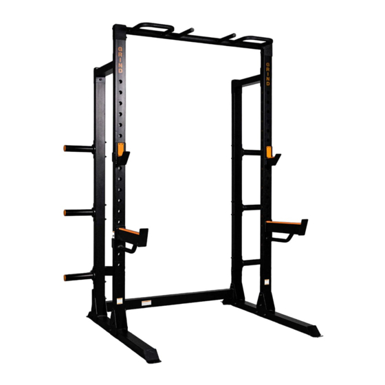
POWER RACK EXERCISER
USER'S MANUAL
C4000 — MODEL NO. GR133
!
WARNING
Read the assembly, installation, care, maintenance, and use instructions in this manual
prior to assembling and using this equipment. Save this manual for future reference.
1
Advertisement

Related Manuals for PRx Performance GRIND FITNESSC4000


Summary of Contents for PRx Performance GRIND FITNESSC4000
- Page 1 GRIND FITNESS POWERED BY PRX PERFORMANCE We are an obsessed group of lifters who believe that access to out-of-this-world equipment and extraordinarily effective programming shouldn't be limited to the filthy rich. Our equipment only works if you GRIND. Download the app and get to work.
- Page 2 GET YOUR WORKOUTS! SCAN ME How you’ll feel after 30 days How you feel now https://thegrindfitness.com/c4000 FREE on the GRIND App* *It only works if you GRIND!
-
Page 3: Important Precautions
IMPORTANT PRECAUTIONS To reduce the risk of serious injury, read all important precaustions and instructions in this manual and all warnings on the rack before using the weight rack. GRIND assumes no responsibility for personal injury or property damage sustained by or through the use of this product. 1. -
Page 4: Part List
PART LIST Key No. Qty. Description Key No. Qty. Description Right Base Plate Left Base Support Plate Cross Bar M10x20mm Bolt Front Upright M10x70mm Bolt Rear Upright M10x95mm Bolt Connect Frame M10 Nut Pull-up Bar M10 Spring Washer Storage Tube M10 Washer Right Weight Rest Bumper... -
Page 5: Exploded Drawing
EXPLODED DRAWING... - Page 6 ASSEMBLY Two adults assembly required. STEP 1 Identify the Right Base (1) and the Left Base (2), and orient them as shown. Attach the Support Plate (14) to Base with M10x- 95mm Bolts (17).
- Page 7 STEP 2 Attach the Rear Upright (5) to the Left Base with two M10x95mm Bolts (17), M10 Spring Washer (19) and M10 Washer (20) as shown.
- Page 8 ASSEMBLY STEP 3 Attach the Cross Bar (3) to Left Base as shown, secure with three M10 Nuts (18). Do not fully tighten the Bolts yet.
- Page 9 STEP 4 Attach the Rear Upright (5) to the Right Base with two M10x95mm Bolts (17), M10 Spring Washer (19) and M10 Washer (20) as shown.
- Page 10 ASSEMBLY STEP 5 Attach the Cross Bar (3) to Left Base as shown, secure with three M10 Nuts (18). Do not fully tighten the Bolts yet.
- Page 11 STEP 6 Attach the Support Plate (14) to Base with M10x- 95mm Bolts (17). 11 11...
- Page 12 ASSEMBLY STEP 7 Attach the Front Upright (4) to the Left Base with two M10x95mm Bolts (17) as shown. Please note the indicated holes are in the position as shown.
- Page 13 STEP 8 Attach the one Support Plate (14) to Left Base as shown, secure with four M10 Nuts (18). Do not fully tighten the Bolts yet. 13 13...
- Page 14 ASSEMBLY STEP 9 Repeat steps 6-8 to assemble another Front Upright (4).
- Page 15 STEP 10 Orient the Connect Frame (6) and Plate (13) as shown, secure with M10X70mm Bolts (16), M10 Spring Washers (19), M10 Washers (20) and M10 Nuts (18) as shown. Then attach the Connect Tube (6) to Front Upright with M10x20mm Bolts (15), M10 Spring Washers (19), M10 Washers (20) as shown.
- Page 16 ASSEMBLY STEP 11 Identify the Pull-up Bar (7) and orient it as shown. Make sure that the long side of the bracket is in the bracket indicated location. Attach the Pull-up Bar (7) to the Front Upright (3) with two M10 x 95mm Bolts (17), an M10 Spring Washer (19), an M10 Washer (20), and an M10 Nut (18);...
- Page 17 STEP 12 See steps 3–11. Tighten all the M10 Nuts (18), M10 x 95mm Bolts (17), M10x70mm Bolts (16)and M10 x 20mm Bolts (15). Next, attach a Storage Tube (8) to the Rear Upright (5) with two M10 x 95mm Bolts (17), two M10 Washers (20), and two M10 Nuts (18).
- Page 18 ASSEMBLY STEP 13 Insert the Right Weight Rest (9) into the desired adjustment hole in the Right Front Upright (4). Then, insert the Right Spotter (11) into an adjustment hole below the Right Weight Rest. Repeat this step on the other side of the weight rack.
-
Page 19: Get To Work
GET TO WORK STEP 14 Scan the QR Code to get your FREE 30-days of programming using the GRIND App. iPhone users can simply open their camera to scan the code. How you’ll feel after 30 days Android users may need to use a scanning app. How you feel now FREE on the GRIND App*... - Page 20 WARNING SERIOUS INJURY OR DEATH COULD OCCUR IF THESE PRECAUTIONS ARE NOT OBSERVED » Always consult a physician before beginning any exercise program » Read and understand warning labels and user manual prior to exercise. Obtain instruction prior to use »...
- Page 21 GRIND Fitness 30-Day Warranty PRx Performance LLC, DBA GRIND Fitness warrants to the original consumer purchaser that this product will be free of defects in material and workmanship for 30 days from the date of purchase. GRIND Fitness will repair or replace the product, at our sole option, in the event of such a defect within the warranty period.
Need help?
Do you have a question about the GRIND FITNESSC4000 and is the answer not in the manual?
Questions and answers