Table of Contents
Advertisement
Advertisement
Table of Contents

Related Manuals for Woods MOW'N MACHINE FZ22-2


Summary of Contents for Woods MOW'N MACHINE FZ22-2
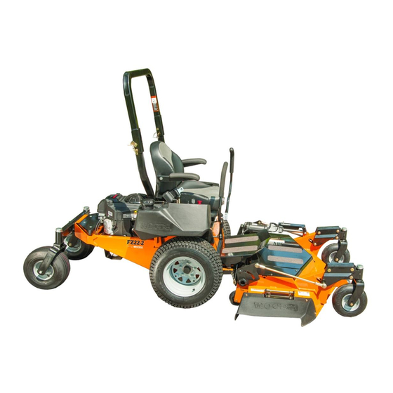
- Page 1 MOW’N MACHINE FZ22-2...
- Page 2 TO THE OWNER: Read this manual before operating your Woods equipment. The information presented will prepare you to do a better and safer job. Keep this manual handy for ready reference. Require all operators to read this manual carefully and become acquainted with all adjustment and operating procedures before attempting to operate.
-
Page 3: Table Of Contents
TABLE OF CONTENTS INTRODUCTION ..........2 SPECIFICATIONS. -
Page 4: Introduction
SPECIFICATIONS Engine: FZ22-2 ......Kawasaki, 4-Cycle, Air Cooled Horsepower: FZ22-2 ......... . . 22 HP Fuel Type: . -
Page 5: Safety Rules
SAFETY RULES ATTENTION! BECOME ALERT! YOUR SAFETY IS INVOLVED! equipment for eyes, hair, hands, hearing, and head; Safety is a primary concern in the design and and respirator or filter mask where appropriate. manufacture of our products. Unfortunately, our Make sure attachment is properly secured, efforts to provide safe equipment can be wiped adjusted, and in good operating condition. - Page 6 SAFETY RULES ATTENTION! BECOME ALERT! YOUR SAFETY IS INVOLVED! Keep hands, feet, hair, and clothing away from (Safety Rules continued from previous page) equipment while engine is running. Stay clear of all Remove gas-powered equipment from the truck moving parts.
- Page 7 SAFETY RULES ATTENTION! BECOME ALERT! YOUR SAFETY IS INVOLVED! Before attempting to unplug vacuum hoses, dis- (Safety Rules continued from previous page) engage PTO, stop power unit, and remove key. Installation of a grasscatcher assembly will reduce the stability and maneuverability of the ...
- Page 8 SAFETY RULES ATTENTION! BECOME ALERT! YOUR SAFETY IS INVOLVED! STORAGE (Safety Rules continued from previous page) Keep children and bystanders away from stor- Tighten all bolts, nuts, and screws to torque age area. chart specifications. Check that all cotter pins are installed securely to ensure equipment is in a safe ...
-
Page 9: Safety Decals
SAFETY & INSTRUCTIONAL DECALS ATTENTION! BECOME ALERT! YOUR SAFETY IS INVOLVED! Replace Immediately If Damaged! 1 – 72407 2 – 72404 3 – SERIAL NUMBER PLATE (Safety Decals continued on next page) Safety 9 MAN1192 (1/13/2017) - Page 10 Replacement safety decals can be ordered free from your Woods dealer, or in the United States and Canada call 1-800-319-6637.
-
Page 11: Operation 11
OPERATION The operator is responsible for the safe operation of tilt position. Release switch when deck reaches maxi- this Mow’n Machine. The operator must be properly mum tilt position. To lower the deck, push and hold tog- trained. Operators should be familiar with the power gle switch until it cycles to the desired cutting height. - Page 12 Make sure people and objects are clear of A safety switch in the operator’s seat will cause the engine to stop if the operator leaves the seat with the attachment and discharge area before engaging PTO or steering handles engaged. The engine will also PTO.
- Page 13 ARNING the steering handles are moved, the faster the machine will move. Steering Handle Positions Watch for hidden hazards on the terrain during operation. NOTICE Practice steering maneuvers at half throttle. ■ If you become confused during operation, return both handles to the center NEUTRAL posi- STEERING HANDLE OPERATION tion and the power unit will stop.
- Page 14 STOPPING ENGINE WEIGHT TRANSFER SYSTEM ARNING CAUTION Remove key and store in a secure location to ■ When using weight transfer system, correct prevent unauthorized persons from operating counterweight must be used to maintain stability. equipment. The weight transfer is designed to place an additional 1.
- Page 15 OWNER PRE-OPERATION CHECK LIST ___ Check to be sure engine is free of dirt and debris. Pay particular attention to the cooling fins, gover- (OWNER'S RESPONSIBILITY) nor parts and muffler. ___ Review and follow all safety rules and safety ___ Do not allow riders. decal instructions on pages 5 through 10.
-
Page 16: Owner Service
OWNER SERVICE ARNING Change Engine Oil NOTICE Before performing any service or maintenance, ■ Use care to prevent hot oil from contacting lower attachment to ground, turn off power unit bare skin. engine, remove key, and disconnect battery ground cable (negative -). - Page 17 Figure 4. Lubrication Diagram TAILWHEEL MAINTENANCE Once a year, disassemble tailwheel assembly and inspect roller bearings: 1. Remove dust cap (2) from top of tailwheel assembly (1). 2. Remove cotter pin (3) and slotted hex nut (4). 3. Remove wheel fork (10), bearing cones (6) and remaining hardware from assembly.
- Page 18 HYDROSTATIC TRANSMISSION SERVICE Service and Maintenance Procedures Some of the service procedures presented on the fol- NOTE: Hydrostatic system should require no servicing lowing pages can be performed while the transaxle is or oil additions between regularly scheduled mainte- mounted on the vehicle. Any repair procedures as nance.
- Page 19 FLUID CHANGE PROCEDURE 13. Re-install the expansion tank cap by hand. Be careful to not over tighten. This transaxle is designed with an external filter for 14. Proceed to the purge procedure. ease of maintenance. To ensure constant fluid quality levels and longer life, an initial oil and filter change at 75-100 hours, then every 400 hours thereafter is rec- PURGING PROCEDURES...
- Page 20 75% charge is indicated. ● Sand down scratches and the edges of areas of 7. Add water if necessary. missing paint and coat with Woods spray paint of matching color (purchase from your Woods BURNISH CLUTCH dealer). ●...
-
Page 21: Dealer Service 21
DEALER SERVICE The information in this section is written for dealer ser- 1. Block up power unit frame so both drive wheels are vice personnel. The repair described here requires off the ground. special skills and tools. If your shop is not properly 2. - Page 22 TROUBLESHOOTING ENGINE PROBLEM POSSIBLE CAUSE SOLUTION Engine will not crank PTO switch is “ON” Switch to the “OFF” position Steering handles are not in “NEU- Pivot steering handles outward TRAL” Battery is discharged Charge or replace battery Starter fuse is blown Replace fuse Steering handle switches are out of Listen for the switch “click”...
- Page 23 Troubleshooting Deck Safety Switch 4. Install screws and nuts in the front and rear of the frame finger tight. 1. Pull handlebars in with deck in lowest cutting 5. With hydro positioned squarely, tighten small L height position (1), see Figure 10. bracket nuts and then the longer screws through 2.
- Page 24 drive wheel rotates with park brake engaged, there 3. Disconnect electrical wire harness from clutch (1). may be internal hydrostatic problems. Contact 4. Remove screw from end of crank shaft. ® authorized Hydro-Gear dealer). 5. Remove clutch from crank shaft. Be sure to 3.
- Page 25 Assembly of this Mow’n Machine is the responsibility of 2. Torque lug bolts to 85 lbs-ft. the Woods dealer. It should be delivered to the owner completely assembled, lubricated, and adjusted for Drive Tire Pressure: normal cutting conditions.
- Page 26 ADJUST STEERING HANDLES for taller operators and the middle and bottom holes are for shorter operators. Do not tighten hardware at this time. Repeat steps 1 and 2 for right steering handle. 3. Rotate handles inward. Align handles with one another.
-
Page 27: Dealer Check Lists 27
DEALER CHECK LISTS PRE-DELIVERY CHECK LIST DELIVERY CHECK LIST (DEALER’S RESPONSIBILITY) (DEALER’S RESPONSIBILITY ___ Show customer how to make adjustments. Inspect the equipment thoroughly after assembly to make sure it is set up properly before delivering it to the ___ Instruct customer how to lubricate and explain customer. - Page 28 NOTES 28 Dealer Check Lists MAN1192 (1/13/2017)
- Page 29 Parts Index Mow’n Machine FZ22-2 FZ22-2 FRAME ASSEMBLY ......30 & 31 ENGINE ASSEMBLY FZ22-2 (Kawasaki Gas Engine 22hp)....32 HYDROSTAT DRIVE SYSTEM.
- Page 30 FZ22-2 FRAME ASSEMBLY 30 Parts MAN1192 (1/13/2017)
- Page 31 FZ22-2 FRAME ASSEMBLY PARTS LIST PART DESCRIPTION PART DESCRIPTION 01563700 Key switch ------- * Battery, 340 CCA 06517400 Panel nut 1044901 Front cover 07517700 Ignition cap 78779 Skid plate 35139 Retainer ring 78606 Console 70179 Plug - 1.25 Sq - Plastic 78607 Decal, instruction 71144...
- Page 32 FZ22-2 ENGINE ASSEMBLY PART DESCRIPTION PART DESCRIPTION 78724 Air pre-filter 75310 Solenoid 78725 Engine tune up kit 75325 Drain valve 12 21536100 Spark plug 75364 Exhaust gasket 78738 Nut, Whiz M8 x 1.25P Flange Stainless 75366 16mm O-ring 62153 3/8 NC x 1 Flange Head Screw Serated 78457 Kawasaki, FS651V 70065 *...
- Page 33 HYDROSTAT DRIVE SYSTEM PART DESCRIPTION PART DESCRIPTION 71206 1/4-20 Flanged hex screw 78454 Hydrostat drive, RT 71851 5/16 NC x 3/4 Flanged cap screw 78455 Hydrostat drive, LT 73163 * 16 5/16 NC Flanged whiz nut 78456 Expansion tank 73955 23 x 10.50 Turf tire &...
- Page 34 PTO, CLUTCH & PUMP ASSEMBLY 34 Parts MAN1192 (1/13/2017)
- Page 35 PTO CLUTCH & PUMP ASSEMBLY PARTS LIST PART DESCRIPTION PART DESCRIPTION 3886 * 1/4 x 1/4 x 1-1/4 Key 78813 Idler arm drive 51880 Flanged idler 78815 Idler arm PTO 62233 .187 X .75 Key Woodruff 1033958 3/8NC x 1-1/4 Flanged screw 64051 5/32 x 5/8 Key Woodruff 14350 *...
- Page 36 SEAT ASSEMBLY PART DESCRIPTION PART DESCRIPTION 1032106 ROPS Folding 78496 Arm rest pad, 13M 78495 Arm rest assembly, LH, 13M 1035001 Hinge pin assembly 78497 2IN Retractable seat belt, 13M 1035002 Anti-rattle spring 78503 4IN Track set, 13M 1035003 ROPS stop 2.0 78700 DCL, Mown Machine 1035004...
- Page 37 STEERING ASSEMBLY PART DESCRIPTION PART DESCRIPTION 765 * 1/2 NC Hex lock nut 71632 5/16 NC X 1 Whiz bolt 1282 1/4 NC x 1/2 Round head screw 72886 Nylon shoulder washer 2290 * 3/8 NC x 2-1/2 HHCS 73023 Steering lever 2472 * 5/16 Lock washer...
- Page 38 38 Parts MAN1192 (1/13/2017)
- Page 39 FZ22-2 WIRING DIAGRAM PARTS LIST PART DESCRIPTION PART DESCRIPTION 71387 Fuse - 7.5 amp auto 78613 FZ22-2 Wiring assembly 78043 Positive battery cable 01563700 Ignition switch w/ terminal boot 75196 Ignition key 78042 Negative battery cable -------- Battery 12V L-Terminals 340CCA 75310 Engine solenoid relay (obtain locally)
- Page 40 WIDE STANCE TAILWHEEL ASSEMBLY PART DESCRIPTION PART DESCRIPTION 5849 3/4 NF Slotted hex nut 3585 Bearing cup 70332 Dust cap 3586 Bearing cone 64291 * Cotter pin, 5/32 x 1 70328 Seal, 1.5 x 2 x .187 62153 * 3/8 NC x 1 Flanged screw SRTD 70086 Spacer, 1.013 x 1.5 x .375 70336...
- Page 41 HEADLIGHT KIT (OPTIONAL) PART DESCRIPTION PART DESCRIPTION 73938 Headlight kit 4378 * 5/16 Flat washer 73937 Light bracket - left 5288 * 1/4 NC Hex nut 73936 Light bracket - right 1985 * 1/4 Lock washer 73935 Rect. work light with switch -------- * Plastic tie 07516000...
- Page 42 78727 COUNTERWEIGHT MOUNT KIT (OPTIONAL) PART DESCRIPTION -------- Weight, 14.8 lb 78728 * 3/8 NC x 8 Carriage bolt GR5, ZP * Standard hardware, obtain locally 42 Parts MAN1192 (1/13/2017)
-
Page 43: Bolt Torque Chart
BOLT TORQUE CHART Always tighten hardware to these values unless a different torque value or tightening procedure is listed for a specific application. Fasteners must always be replaced with the same grade as specified in the manual parts list. Always use the proper tool for tightening hardware: SAE for SAE hardware and Metric for metric hardware. Make sure fastener threads are clean and you start thread engagement properly. - Page 44 BOLT SIZE CHART NOTE: Chart shows bolt thread sizes and corresponding head (wrench) sizes for standard SAE and metric bolts. SAE Bolt Thread Sizes 5/16 Metric Bolt Thread Sizes 10MM 12MM 14MM 16MM 18MM ABBREVIATIONS AG .............. Agriculture MPa............Mega Pascal ASABE ....American Society of Agricultural &...
-
Page 45: Index 45
INDEX ASSEMBLY Owner Pre-Operation Checklist (Owner’s Responsibility) Dealer Set-Up Instructions Practice Operation Install Single Tailwheel (Optional) Uneven Terrain Operation DEALER CHECK LISTS Safety Switch System Delivery (Dealer’s Responsibility) Start Engine Pre-Delivery (Dealer’s Responsibility) Cold Weather Starting Tips Start Mower or Attachment DEALER SERVICE Stop Mower or Attachment Belt Removal... - Page 46 , the Woods logo and Mow’n Machine are trademarks of Woods Equipment Com- pany. All other trademarks, trade names, or service marks not owned by Woods Equipment Company that appear in this manual are the property of their respective companies or mark holders. Specifications subject to change without notice.
- Page 47 WHAT WOODS WILL DO TO CORRECT PROBLEMS: WOODS’ obligation under this Warranty is limited to, at WOODS’ option, the repair or replacement, free of charge, of the product if the product is defective or in noncompliance with this Warranty. The product must be returned to WOODS with proof of purchase within thirty (30) days after such defect or noncompliance is discovered or should have been discovered, routed through the dealer and distributor from whom the purchase was made, transportation charges prepaid.
- Page 48 Woods logo are trademarks of Woods Equipment Company. All other trademarks, trade names, or service marks not owned by Woods Equipment Company that appear in this manual are the property of their respec- tive companies or mark holders. Specifications subject to change without notice.
Need help?
Do you have a question about the MOW'N MACHINE FZ22-2 and is the answer not in the manual?
Questions and answers