Table of Contents
Advertisement
Quick Links
Advertisement
Table of Contents

Related Manuals for Analytic Systems BCD600-32-12


Summary of Contents for Analytic Systems BCD600-32-12
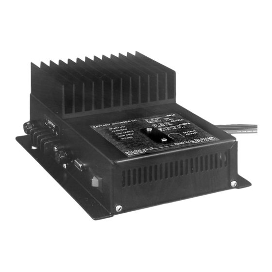
- Page 1 BCD600 Series Battery Charger DC Installation & Operation Manual...
-
Page 2: Important Safety Instructions
IMPORTANT SAFETY INSTRUCTIONS SAVE THESE INSTRUCTIONS — This manual contains important safety and operating instructions for the battey charger. ALL BATTERY CHARGERS 1) CAUTION — To reduce risk of injury, charge only lead acid or sealed gel cell type rechargeable batteries. Other types of batteries may burst causing personal injury and damage. -
Page 3: Battery Charger Location
Connect and disconnect all DC connections only after setting battery charger switch to off position. Analytic Systems does not recommend the use of the BCD600 Series DC Battery Chargers in life support applications where failure or malfunction of this product can be reasonably expected to cause failure of the life support device or to significantly affect its safety or effectiveness. -
Page 4: Specifications
Fastenings 18-8 Stainless 4.0 lb / 1.8 kg Weight * This is Analytic Systems’ suggested range. Please consult your battery manufacturer for their recommendations. Designed and manufactured by: ANALYTIC SYSTEMS WARE (1993) LTD. #207 12448 82 Ave. Surrey, B.C., V3W 3E9, Canada... - Page 5 Installation: Allow at least 1 inch of clearance all around the case for cooling. The best OUTPUT mounting configuration is to mount the FUSE unit on a vertical surface oriented as shown. Use #10 screws of the appropriate type for the mounting surface to securely mount the unit.
- Page 6 When the unit is first turned on, it will charge the batteries at a constant current of 50 amps for a –12 model and 38 amps for a –24 model. During this time, the red ‘Charging’ LED will be on. If the batteries are seriously discharged, the ‘Low Output’...
- Page 7 Dry Contact Relay To use your dry contact output fail relay you must connect a 9-pin D connector to the unit. You must use pins one and six as is indicated on page 8 in the remote control diagram. The relay is factory preset to fail in the closed position when the low output LED and buzzer come on.
-
Page 8: Remote Connector
REMOTE CONNECTOR This connector is located on the side of the unit. Note: All switches are electronic (solid state) not mechanical relays. REMOTE CONTROL A remote control panel may be connected to the inverter using a 9- pin D-connector which attaches to the front panel of the battery charger. - Page 9 This page left intentionally blank.
- Page 10 Limited Warranty The equipment manufactured by Analytic Systems Ware (1993) Ltd. (the “Warrantor”) is warranted to be free from defects in workmanship and materials under normal use and service. This warranty is in effect for 3 years from the date of purchase by the user (the “Purchaser”).
Need help?
Do you have a question about the BCD600-32-12 and is the answer not in the manual?
Questions and answers