Table of Contents
Advertisement
Quick Links
Advertisement
Table of Contents

Related Manuals for Lantech IPES-2204F


Summary of Contents for Lantech IPES-2204F
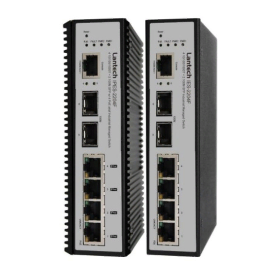
- Page 1 Lantech IPES-2204F / IES-2204F User Manual V2.2 Aug. 2017...
-
Page 2: Table Of Contents
Table of Content Chapter 1 Introduction ..........1 Package Contents .......... 4 Chapter 2 Hardware Description ......5 Bottom View ........... 5 LED Indicators..........6 Chapter 3 Hardware Installation ......8 Installation Steps ..........8 DIN-Rail Mounting .......... 9 Wall Mount Plate Mounting ......11 Wiring the Power Inputs ....... - Page 3 IP Addressing – IPV4 ........29 Syslog ............31 Syslog Configuration ............. 31 SNMP Configuration ........32 SNMP - Agent ............... 32 6.20.1 SNMP Trap Configuration ......34 5.10 System Alert - Relay Alarm ......35 6.8.1 System Alert - SMTP ........35 6.8.2 System Alert - Event ........
- Page 4 6.26. Security ............. 56 6.26.1 IP Source Guard - Configuration ....56 IP Source Guard – Static Table ....57 6.26.2 6.27. Maintenance ..........58 6.27.1 Save Configuration ........58 Troubles shooting............ 63 Appendix A—RJ-45 Pin Assignment ..... 64 RJ-45 Pin Assignments .......... 64 RJ-45 Pin Assignment of PoE ........
- Page 5 Recommendation for Shielded network cables STP cables have additional shielding material that is used to reduce external interference. The shield also reduces the emission at any point in the path of the cable. Our recommendation is to deploy an STP network cable in demanding electrical environments. Examples of demanding indoor environments are where the network cable is located in parallel with electrical mains supply cables or where large inductive loads such as motors or contactors are in close vicinity to the camera or its cable.
- Page 6 FCC Warning This Equipment has been tested and found to comply with the limits for a Class-A digital device, pursuant to Part 15 of the FCC rules. These limits are designed to provide reasonable protection against harmful interference in a residential installation. This equipment generates, uses, and can radiate radio frequency energy.
-
Page 7: Chapter 1 Introduction
Chapter 1 Introduction The Lantech IPES-2204Fand IES-2204F are Smart Redundant Ring Ethernet switches with 4 10/100TX + 2 100M SFP ports Industrial Switch. The IPES-2204F built in 4-port PoE injectors, feeding up to 30W per port. IPES-2204F-48V 4 10/100TX PoE at/af + 2 100M SFP, 45~56VDC, -20~60˚C IPES-2204F-48V-E 4 10/100TX PoE at/af + 2 100M SFP, 45~56VDC, -40~75˚C... - Page 8 Supports 10 IP addresses that have permission to access IP Security the switch management and to prevent unauthorized intruder. Support ingress packet filter and egress packet limit The egress rate control supports all of packet type and the limit rates are 100K~102400Kbps(10/100), 100K~256000Kbps(1000) Bandwidth Ingress filter packet type combination rules are...
- Page 9 Each port allows importing 128bits of alphabetic string of ifAlias word on SNMP interface...
-
Page 10: Package Contents
1.1 Package Contents Please refer to the package content list below to verify them against the checklist. Managed Industrial Switch x 1 User manual x 1 Pluggable Terminal Block x 1 RJ-45 to DB9-Female cable x 1 Compare the contents of the industrial switch with the standard checklist above. -
Page 11: Chapter 2 Hardware Description
Chapter 2 Hardware Description 2.1 Bottom View The bottom panel of the Industrial Managed Industrial Switch has one terminal block connector of two DC power inputs and one fault alarm. Bottom Panel of the industrial switch... -
Page 12: Led Indicators
2.2 LED Indicators Front Panel of IES-2204F and IPES-2204F The diagnostic LEDs that provide real-time information of system and optional status are located on the front panel of the industrial switch. The following table provides the description of the LED status and their meanings for the switch. - Page 13 The industrial switch is not a ring master in Pro-Ring2s group Power 1 is active PWR1 Green Power 1 is inactive Power 2 is active PWR2 Green Power 2 is inactive Power or port failure FAULT No failure A network device is detected. P5, P6 The port is transmitting or receiving packets Green...
-
Page 14: Chapter 3 Hardware Installation
Chapter 3 Hardware Installation In this paragraph, we will describe how to install the Pro-Ring2s Managed Industrial Switch and the installation points attended to it. 3.1 Installation Steps 1. Unpack the Industrial switch 2. Check if the DIN-Rail is screwed on the Industrial switch or not. If the DIN-Rail is not screwed on the Industrial switch, please refer to DIN-Rail Mounting section for DIN- Rail installation. -
Page 15: Din-Rail Mounting
3.2 DIN-Rail Mounting The DIN-Rail is screwed on the industrial switch when out of factory. If the DIN-Rail is not screwed on the industrial switch, please see the following pictures to screw the DIN- Rail on the switch. Follow the steps below to hang the industrial switch. - Page 16 First, insert the top of DIN-Rail into the track. Then, lightly push the DIN-Rail into the track. Check if the DIN-Rail is tightened on the track or not. To remove the industrial switch from the track, reverse above steps.
-
Page 17: Wall Mount Plate Mounting
3.3 Wall Mount Plate Mounting Follow the steps below to mount the industrial switch with wall mount plate. 1. Remove the DIN-Rail from the industrial switch; loose the screws to remove the DIN- Rail. 2. Place the wall mount plate on the rear panel of the industrial switch. 3. -
Page 18: Wiring The Power Inputs
Please follow the steps below to insert the power wire. 1. Insert AC or DC power wires into the contacts 1 and 2 for power 1, or 5 and 6 for power. 2. Tighten the wire-clamp screws for preventing the wires from loosing. IPES-2204F-48V 45~56VDC IPES-2204F-48V-E 45~56VDC IPES-2204F-12V 9.5~56VDC... -
Page 19: Wiring The Fault Alarm Contact
3.5 Wiring the Fault Alarm Contact The fault alarm contacts are in the middle of the terminal block connector as the picture shows below. Inserting the wires, the switch will detect the fault status of the power failure, or port link failure (available for managed model) and then forms an open circuit. The following illustration shows an application example for wiring the fault alarm contacts. -
Page 20: Cabling
3.6 Cabling Use four twisted-pair, Category 5e or above cabling for RJ-45 port connection. The cable between the switch and the link partner (switch, hub, workstation, etc.) must be less than 100 meters (328 ft.) long. Fiber segment using single-mode connector type must use 9/125 µm single-mode fiber cable. - Page 21 To connect the transceiver and LC cable, please follow the steps shown below: First, insert the transceiver into the SFP module. Notice that the triangle mark is the bottom of the module. Transceiver to the SFP module Transceiver Inserted Second, insert the fiber cable of LC connector into the transceiver.
- Page 22 LC connector to the transceiver...
- Page 23 To remove the LC connector from the transceiver, please follow the steps shown below: First, press the upper side of the LC connector to release from the transceiver and pull it out. Remove LC connector Second, push down the metal loop and pull the transceiver out by the plastic handle. Pull out from the transceiver...
-
Page 24: Chapter 4 Console Management
Chapter 4 Console Management 4.1 Connecting to the Console Port The supplied cable which one end is RS-232 connector and the other end is RJ-45 connector. Attach the end of RS-232 connector to PC or terminal and the other end of RJ-45 connector to the console port of the switch. -
Page 25: Login In The Console Interface
4.3 Login in the Console Interface When the connection between Switch and PC is ready, turn on the PC and run a terminal emulation program or Hyper Terminal and configure its communication parameters to match the following default characteristics of the console port: Baud Rate: 9600 bps Data Bits: 8 Parity: none... -
Page 26: Cli Management
4.4 CLI Management The system supports the console management—CLI command. After you log in on to the system, you will see a command prompt. To enter CLI management interface, type in “enable” command. CLI command interface... -
Page 27: Chapter 5 Web-Based Management
Chapter 5 Web-Based Management This section introduces the configuration and functions of the Web-Based management. 5.1 About Web-based Management There is an embedded HTML web site residing in flash memory on CPU board of the switch, which offers advanced management features and allows users to manage the switch from anywhere on the network through a standard browser such as Microsoft Internet Explorer. -
Page 28: System Login
5.3 System Login Launch the Internet Explorer on the PC Key in “http:// “+” the IP address of the switch”, and then Press “Enter”. The login screen will appear right after Key in the user name and password. The default user name and password are the same as ‘root’. -
Page 29: System
5.4 System 6.4.1 General – Switch Information User can find the system name, description, location and contact personnel to identify the switch. The version table below is a read-only field to show the basic information of the switch. System Name: Assign the system name of the switch (The maximum length is 64 bytes) ... - Page 30 6.4.2 General – CPU Load Average Sometimes the user was worry about that ‘ Could my switch process too many network packets ? So the network throughput was keeping decreasing “. In this option, you can monitor the CPU of switch to see if the switch was in full loading status or not.
-
Page 31: Time - Sntp
5.5 Time - SNTP SNTP (Simple Network Time Protocol) is a simplified version of NTP which is an Internet protocol used to synchronize the clocks of computers to some time reference. Because time usually just advances, the time on different node stations will be different. With the communicating programs running on those devices, it would cause time to jump forward and back, a non-desirable effect. - Page 32 PDT - Pacific Daylight PST - Pacific Standard -8 hours 4 am ADT - Alaskan Daylight ALA - Alaskan Standard -9 hours 3 am HAW - Hawaiian -10 hours 2 am Standard Nome, Alaska -11 hours 1 am CET - Central European FWT - French Winter MET - Middle European +1 hour...
- Page 33 Guam Standard, USSR Zone 9 IDLE - International Date Line NZST - New Zealand +12 hours Midnight Standard NZT - New Zealand SNTP Sever Address: Set the SNTP server IP address. You can assign a local network time server IP address or an internet time server IP address. ...
-
Page 34: Account - Admin
SNTP Configuration interface 5.6 Account - Admin Change web management login user name and password for the management security issue. User name: Type in the new user name (The default is ‘root’) New Password: Type in the new password (The default is ‘root’) ... -
Page 35: Ip Addressing - Ipv4
5.7 IP Addressing – IPV4 The switch is a network device which needs to be assigned an IP address for being identified on the network. Users have to decide a means of assigning IP address to the switch. DHCP Client: Enable or disable the DHCP client function. When DHCP client function is enabled, the switch will be assigned an IP address from the network DHCP server. - Page 36 IP Addressing interface...
-
Page 37: Syslog
5.8 Syslog This page allows the user to decide whether to send the system event log, and select the mode which the system event log will be sent to client only, server only, or both client and server. What kind of event log will be issued to the client/server depends on the selection on the Event Configuration tab. -
Page 38: Snmp Configuration
5.9 SNMP Configuration Simple Network Management Protocol (SNMP) is the protocol developed to manage nodes (servers, workstations, routers, switches and hubs etc.) on an IP network. SNMP enables network administrators to manage network performance, find and solve network problems, and plan for network growth. Network management systems learn of problems by receiving traps or change notices from network devices implementing SNMP. - Page 39 SNMP Agent Configuration interface...
-
Page 40: Snmp Trap Configuration
6.20.1 SNMP Trap Configuration A trap manager is a management station that receives the trap messages generated by the switch. If no trap manager is defined, no traps will be issued. To define a management station as a trap manager, assign an IP address, enter the SNMP community strings, and select the SNMP trap version. -
Page 41: System Alert - Relay Alarm
5.10 System Alert - Relay Alarm The Fault Relay Alarm function provides the Power Failure and Port Link Down/Broken detection. With both power input 1 and power input 2 installed and the check boxes of power 1/power 2 ticked, the FAULT LED indicator will then be possible to light up when any one of the power failures occurs. - Page 42 function provides the authentication mechanism including an authentication step through which the client effectively logs in to the SMTP server during the process of sending e- mail alert. Email Alert: With this function being enabled, the user is allowed to configure the detail settings for sending the e-mail alert to the SMTP server when the events occur.
-
Page 43: System Alert - Event
6.8.2 System Alert - Event Having ticked the Syslog/SMTP checkboxes, the event log/email alert will be sent to the system log server and the SMTP server respectively. Also, Port event log/alert (link up, link down, and both) can be sent to the system log server/SMTP server respectively by setting the trigger condition. - Page 44 Event Configuration interface...
-
Page 45: Port - Configuration
5.11 Port - Configuration In Port control you can configure the settings of each port to control the connection parameters, and the status of each port is listed beneath. Port No.: The port number which you want to be configured. ... -
Page 46: Port Status
5.12 Port Status It will show you the status of port configuration setting . -
Page 47: Port Statistics
5.13 Port Statistics The following chart provides the current statistic information which displays the real-time packet transfer status for each port. The user might use the information to plan and implement the network, or check and find the problem when the collision or heavy traffic occurs. -
Page 48: Port - Port Alert
Port – Port Alert 5.14 Having ticked the Syslog/SMTP checkboxes, the event log/email alert will be sent to the system log server and the SMTP server respectively. Also, Port event log/alert (link up, link down, and both) can be sent to the system log server/SMTP server respectively by setting the trigger condition. -
Page 49: Rate Control -Rate Limit
Rate Control –Rate Limit 5.15 You can set up every port’s bandwidth rate and frame limitation type. All the ports support port egress rate control. For example, assume port 1 is 10Mbps, users can set it’s effective egress rate is 1Mbps, ingress rate is 500Kbps. The switch performs the ingress rate by packet counter to meet the specified rate ... - Page 50 Broadcast/Multicast/Flooded Unicast Broadcast/Multicast Broadcast only Broadcast/Multicast/Flooded Unicast, Broadcast/Multicast and Bbroadcast only types are only for ingress frames. The egress rate only supports All type. And then, click to apply the settings Apply...
-
Page 51: Spanning Tree
5.16 Spanning Tree The Rapid Spanning Tree Protocol (RSTP) is an evolution of the Spanning Tree Protocol and provides for faster spanning tree convergence after a topology change. The system also supports STP and the system will auto-detect the connected device that is running STP or RSTP protocol. - Page 52 the port concerned can only be connected to exactly another bridge (i.e. it is served by a point-to-point LAN segment), or can be connected to two or more bridges (i.e. it is served by a shared medium LAN segment). This function allows the P2P status of the link to be manipulated administratively.
-
Page 53: Rstp Information
6.18.2 RSTP Information This web page provides the port and switch information about RSTP. RSTP System Configuration interface... -
Page 54: Pro-Ring Ii Se
5.17 Pro-Ring II SE Pro-Ring IIs is a new Ring mechanism for Lantech Industrial Switches in which it protects the network by flexible topology than ever. Pro-Ring IIs works as a Single Ring and Multiple Ring to recover the broken ring in less than 20 ms for up to 50 switch nodes.. -
Page 55: Lldp
5.18 LLDP Link Layer Discovery Protocol (LLDP) is defined in the IEEE 802.1AB, it is an emerging standard which provides a solution for the configuration issues caused by expanding LANs. LLDP specifically defines a standard method for Ethernet network devices such as switches, routers and wireless LAN access points to advertise information about themselves to other nodes on the network and store the information they discover. -
Page 56: Lldp Neighbors
6.22.1 LLDP Neighbors It will show you the information about Port Neighbor via LLDP protocol. -
Page 57: Vlan
6.23 VLAN A Virtual LAN (VLAN) is a logical network grouping that limits the broadcast domain, which would allow you to isolate network traffic, so only the members of the same VLAN will receive traffic from the ones of the same VLAN. Basically, creating a VLAN on a switch is logically equivalent of reconnecting a group of network devices to another Layer 2 switch. -
Page 58: Qos
6.24 QoS Quality of Service (QoS) is the ability to provide different priority to different applications, users or data flows, or to guarantee a certain level of performance to a data flow. QoS guarantees are important if the network capacity is insufficient, especially for real-time streaming multimedia applications such as voice over IP or Video Teleconferencing, since these often require fixed bit rate and are delay sensitive, and in networks where the capacity is a limited resource, for example in cellular data communication. -
Page 59: Port Priority
6.25.2 Port Priority Configure the priority level for each port. With the drop-down selection item of Priority Type above being selected as Port-based, this control item will then be available to set the queuing policy for each port. Port x: Each port has 4 priority levels—High, Middle, Low, and Lowest—to be chosen. -
Page 60: Cos Mapping To Queue
6.25.3 COS Mapping to Queue Set up the COS priority level. With the drop-down selection item of Priority Type above being selected as COS only/COS first, this control item will then be available to set the queuing policy for each port. ... -
Page 61: Dscp Mapping To Queue
6.25.4 DSCP mapping to queue Set up the DSCP priority. With the drop-down selection item of Priority Type above being selected as DSCP only/SDCP first, this control item will then be available to set the queuing policy for each port. ... -
Page 62: Security
6.26. Security You can block the un-authorized client in this function. 6.26.1 IP Source Guard - Configuration IP Source Guard function allows the user to assign 10 specific IP addresses that have permission to manage the switch through the http and telnet services for the securing switch management. -
Page 63: Ip Source Guard - Static Table
6.26.2 IP Source Guard – Static Table Security IP 1 ~ 10: The system allows the user to assign up to 10 specific IP addresses for access security. Only these 10 IP addresses can access and manage the switch through the HTTP/Telnet service once IP Security Mode is enabled. ... -
Page 64: Maintenance
6.27. Maintenance 6.27.1 Save Configuration Save the current setting of switch .. 6.27.2 Restart Device Make the switch warm start. 6.27.3 Factory Defaults Reset switch to default configuration. Click “Reset” to reset all configurations to the default value. - Page 65 6.27.4 Firmware Upgrade TFTP Server IP Address: Type in your TFTP server IP. Firmware File Name: Type in the name of the firmware image file to be updated. Click Upgrade You can also browser the firmware on your hard drive by web update.
- Page 66 6.27.5 Export/Import You can restore a previous backup configuration from the TFTP server to recover the settings. Before doing that, you must locate the image file on the TFTP server first and the switch will download back the flash image. ...
- Page 67 6.27.6 Diagnostics 6.27.6.1 Ping You can ping other network device in this function. 6.27.6.2 DDM Port No.: Specify the SFP port and show the SFP module information. Temperature: Display the internal temperature of the SFP default threshold and present value. ...
- Page 68 TX PWR: Display the transmission power of the SFP default threshold and present value. RX PWR: Display the received power of the SFP default threshold and present value. Syslog/SMTP: The port will send an e-mail or log on local to administrator when detecting the exceptional value.
-
Page 69: Troubles Shooting
Troubles shooting Verify that is using the right power cord/adapter (DC 24-48V), please don’t use the power adapter with DC output higher than 48V, or it may damage this device. Select the proper UTP/STP cable to construct the user network. Use unshielded twisted-pair (UTP) or shield twisted-pair (STP) cable for RJ-45 connections that depend on the connector type the switch equipped: 100Ω... -
Page 70: Appendix A-Rj-45 Pin Assignment
Appendix A—RJ-45 Pin Assignment RJ-45 Pin Assignments The UTP/STP ports will automatically sense for Fast Ethernet (10Base-T/100Base-TX connections), or Gigabit Ethernet (10Base-T/100Base-TX/1000Base-T connections). Auto MDI/MDIX means that the switch can connect to another switch or workstation without changing straight through or crossover cabling. See the figures below for straight through and crossover cable schematic. - Page 71 10/100Base-TX Cable Schematic The following two figures show the 10/100Base-TX cable schematic. Straight-through cable schematic Cross over cable schematic 10/100/1000Base-TX Pin outs The following figure shows the 10/100/1000 Ethernet RJ-45 pin outs. 10/100/1000Base-TX Cable Schematic...
- Page 72 Straight through cables schematic Cross over cables schematic...
-
Page 73: Pin Assignment Of Poe
RJ-45 Pin Assignment of PoE With 100BASE-TX/10BASE-T cable, pins 1 and 2 are used for transmitting data, and pins 3 and 6 for receiving data; pins 4, 5, 7 and 8 are used for power supplying. Pin out of Cisco non-802.3af standard PD Signal VCC - VCC -... - Page 74 Pin out of PoE Endspan Hub/Switch Signal / Name TX+/VCC+ TX-/VCC+ TX+/VCC- TX-/VCC- ‘+’ and ‘-‘ signs represent the polarity of the wires that make up each wire pair. Note Before you power PD, please check the RJ-45 connector pin assignment follow IEEE802.3af standard;...
Need help?
Do you have a question about the IPES-2204F and is the answer not in the manual?
Questions and answers