
Related Manuals for Lantech IMR-3002


Summary of Contents for Lantech IMR-3002
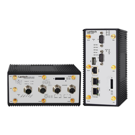
- Page 1 IMR-3002 Industrial Multifunction VPN Router w/ up to 2 LTE 4G + 2 serial ports + 2 Gigabit Ethernet Switch User Manual (Hardware) Apr. 2020...
- Page 2 Recommendation for Shielded network cables STP cables have additional shielding material that is used to reduce external interference. The shield also reduces the emission at any point in the path of the cable. Our recommendation is to deploy an STP network cable in demanding electrical environments.
- Page 3 Lantech Communications Global Inc. Products offered may contain software which is proprietary to Lantech Communications Global Inc. The offer or supply of these products and services does not include or infer any transfer of ownership.
- Page 4 FCC Warning This Equipment has been tested and found to comply with the limits for a Class-A digital device, pursuant to Part 15 of the FCC rules. These limits are designed to provide reasonable protection against harmful interference in a residential installation. This equipment generates, uses, and can radiate radio frequency energy.
-
Page 5: Table Of Contents
Content Hardware Description......2 1.1. Physical Dimension ........2 1.2. IP Protection ..........3 1.3. Front Panel ........... 6 1.4. LED Indicators ..........7 Hardware Installation ......8 2.1. Hardware installation ........8 2.2. DIN-Rail Mounting ........8 2.3. Wall Mount Plate Mounting .......10 2.4. -
Page 6: Hardware Description
1. Hardware Description Lantech IMR-3002 series is a next generation industrial multi-function VPN router. In this paragraph, it will describe the Industrial multi-function VPN router’s hardware spec, port, cabling information, and wiring installation. 1.1. Physical Dimension Metal case. IP-30, 74(W) x 112 (D) x 152 (H) mm... -
Page 7: Ip Protection
1.2. IP Protection The IP Code, Ingress Protection Rating, sometimes also interpreted as International Protection Rating, classifies and rates the degree of protection provided against the intrusion (including body parts such as hands and fingers), dust, accidental contact, and water in mechanical casings and with electrical enclosures. It is published by the International Electrotechnical Commission (IEC) Solid particle protection The first digit indicates the level of protection that the enclosure provides against access... - Page 8 Liquid ingress protection The second digit indicates the level of protection that the enclosure provides against harmful ingress of water. Protected Level Testing for Details against — — protected Dripping Dripping water (vertically Test duration: 10 minutes water falling drops) shall have no Water equivalent to 1 mm harmful effect.
- Page 9 distance of 3 m Powerful Water projected in Test duration: at least water jets powerful jets (12.5 mm 3 minutes nozzle) against the Water volume: 100 litres per enclosure from any minute direction shall have no Pressure: 100 kPa at harmful effects.
-
Page 10: Front Panel
effects. — Powerful Protected against close- high range high pressure, high temperature temperature spray downs. water jets 1.3. Front Panel... -
Page 11: Led Indicators
1.4. LED Indicators The diagnostic LEDs that provide real-time information of system and optional status are located on the front panel of the industrial device. The following table provides the description of the LED status and their meanings for the device. Color Status Meaning... -
Page 12: Hardware Installation
2. Hardware Installation Hardware installation 2.1. 1. Unpack the device 2. Check if the DIN-Rail is screwed on the Industrial device or not. If the DIN-Rail is not screwed on the Industrial device, please refer to DIN-Rail Mounting section for DIN-Rail installation. - Page 13 First, insert the top of DIN-Rail into the track. Then, lightly push the DIN-Rail into the track.
-
Page 14: Wall Mount Plate Mounting
Check if the DIN-Rail is tightened on the track or not. To remove the industrial device from the track, reverse above steps. 2.3. Wall Mount Plate Mounting Follow the steps below to mount the industrial device with wall mount plate. 1. -
Page 16: Wiring The Power Inputs
2.4. Wiring the Power Inputs Please follow the steps below to insert the power wire. 1. Insert AC or DC power wires into the contacts 1 and 2 for power 1, or 5 and 6 for power. 2. Tighten the wire-clamp screws for preventing the wires from loosing. [NOTE] The wire gauge for the terminal block should be in the range between 12 ~ 24 AWG. -
Page 17: Wiring The Fault Alarm Contact
2.5. Wiring the Fault Alarm Contact The fault alarm contacts are in the middle of the terminal block connector as the picture shows below. Inserting the wires, the device will detect the fault status of the power failure, or port link failure (available for managed model) and then forms an open circuit. The following illustration shows an application example for wiring the fault alarm contacts. -
Page 18: Cabling
2.6. Cabling Use four twisted-pair, Category 5e or above cabling for RJ-45 port connection. The cable between the switch and the link partner (switch, hub, workstation, etc.) must be less than 100 meters (328 ft.) long. 2.7. SIM 1. Turn off power of the device. 2. - Page 19 Located on the bottom of the SIM card slot. For LTE2 slot Insert the SIM card into the SIM card slot with the gold contacts facing up. Located on the bottom of the SIM card slot.
-
Page 20: Serial Ports
2.8. Serial Ports Connect the DB9 connector with RS232/RS422/RS485 cable with the following PIN assignment PIN Assignment of RS232 PIN Assignment of RS-422 PIN Assignment of RS-485... -
Page 21: Console Management
3. Console Management 3.1. Connecting to the Console Port The supplied cable which one end is RS-232 connector and the other end is RJ-45 connector. Attach the end of RS-232 connector to PC or terminal and the other end of RJ-45 connector to the console port of the device. -
Page 22: Login In The Console Interface
3.2. Login in the Console Interface When the connection between Device and PC is ready, turn on the PC and run a terminal emulation program or Hyper Terminal and configure its communication parameters to match the following default characteristics of the console port: Baud Rate:115200 bps Data Bits: 8 Parity: none... - Page 23 Console login interface ===============Notice=============== For web-based management, please refer to our “Software Management Manual”. Please contact support@lantechcom.tw for more information.
Need help?
Do you have a question about the IMR-3002 and is the answer not in the manual?
Questions and answers