Advertisement
Quick Links
Advertisement

Related Manuals for Lantech TPGS-0008CA


Summary of Contents for Lantech TPGS-0008CA
- Page 1 T(P)GS-0008CA 8 10/100/1000T Unmanaged (PoE at/af) Ethernet Switch T(P)ES-0008CA 8 10/100TX Unmanaged (PoE at/af) Ethernet Switch T(P)GS-0006CA 6 10/100/1000T Unmanaged (PoE at/af) Ethernet Switch T(P)ES-0006CA 6 10/100TX Unmanaged (PoE at/af) Ethernet Switch User Manual Aug 2021...
- Page 2 Recommendation for Shielded network cables STP cables have additional shielding material that is used to reduce external interference. The shield also reduces the emission at any point in the path of the cable. Our recommendation is to deploy an STP network cable in demanding electrical environments. Examples of demanding indoor environments are where the network cable is located in parallel with electrical mains supply cables or where large inductive loads such as motors or contactors are in close vicinity to the camera or its cable.
- Page 3 Lantech Communications Global Inc. Products offered may contain software which is proprietary to Lantech Communications Global Inc. The offer or supply of these products and services does not include or infer any transfer of ownership.
- Page 4 FCC Warning This Equipment has been tested and found to comply with the limits for a Class-A digital device, pursuant to Part 15 of the FCC rules. These limits are designed to provide reasonable protection against harmful interference in a residential installation. This equipment generates, uses, and can radiate radio frequency energy.
-
Page 5: Table Of Contents
Content Chapter 1 Introduction ..........5 Chapter 2 Hardware Description ......6 Physical Dimension ........6 Package Content:......... 10 IP Protection ..........11 LED Indicators..........14 Chapter 3 Hardware Installation ......15... -
Page 6: Chapter 1 Introduction
Chapter 1 Introduction Lantech T(P)GS/ T(P)ES-0008CA Series are 8 10/100/1000T or 10/100 Base-TX with M12-connctor unmanaged industrial switches for IP41 or IP54 rated protection, which meet the high reliability requirements demanded by industrial applications. Lantech T(P)GS/ T(P)ES-0006CA Series are 6 10/100/1000T or 10/100 Base-TX with M12-connctor unmanaged industrial switches for IP41 or IP54 rated protection. -
Page 7: Chapter 2 Hardware Description
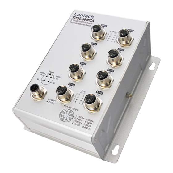
Chapter 2 Hardware Description In this paragraph, it will describe the Industrial switch’s hardware spec, port, cabling information, and wiring installation. 2.1 Physical Dimension T(P)GS-0008CA-54 Aluminum case. IP-54, 135mm(W)x165mm(H)x76.5mm(D) T(P)GS-0008CA-41 Aluminum case. IP-41, 135mm(W)x165mm(H)x76mm(D) - Page 8 T(P)ES-0008CA-54 Aluminum case. IP-54, 135mm(W)x165mm(H)x76.5mm(D) T(P)ES-0008CA-41 Aluminum case. IP-41, 135mm(W)x165mm(H)x76mm(D)
- Page 9 T(P)GS-0006CA-54 Aluminum case. IP-54, 135mm(W)x165mm(H)x76.5mm(D)
- Page 10 T(P)GS-0006CA-41 Aluminum case. IP-41, 135mm(W)x165mm(H)x76mm(D) T(P)ES-0006CA-54 Aluminum case. IP-54, 135mm(W)x165mm(H)x76.5mm(D)
-
Page 11: Package Content
T(P)ES-0006CA-41 Aluminum case. IP-41, 135mm(W)x165mm(H)x76mm(D) 2.2 Package Content: Ethernet Switch Manual CD* *By request... -
Page 12: Ip Protection
2.3 IP Protection The IP Code, Ingress Protection Rating, sometimes also interpreted as International Protection Rating, classifies and rates the degree of protection provided against the intrusion (including body parts such as hands and fingers), dust, accidental contact, and water in mechanical casings and with electrical enclosures. It is published by the International Electrotechnical Commission (IEC) Solid particle protection The first digit indicates the level of protection that the enclosure provides against access... - Page 13 Liquid ingress protection The second digit indicates the level of protection that the enclosure provides against harmful ingress of water. Protected Level Testing for Details against — — protected Dripping Dripping water (vertically Test duration: 10 minutes water falling drops) shall have no Water equivalent to 1 mm harmful effect.
- Page 14 Powerful Water projected in powerful Test duration: at least water jets jets (12.5 mm nozzle) 3 minutes against the enclosure from Water volume: 100 litres per any direction shall have no minute harmful effects. Pressure: 100 kPa at distance of 3 m Immersion Ingress of water in harmful Test duration: 30 minutes...
-
Page 15: Led Indicators
2.4 LED Indicators The diagnostic LEDs that provide real-time information of system and optional status are located on the front panel of the industrial switch. The following table provides the description of the LED status and their meanings for the switch. Color Status Meaning... -
Page 16: Chapter 3 Hardware Installation
Chapter 3 Hardware Installation 3.1Hardware installation For PoE models: If this switch needs to uplink with another switch via a PoE copper port, please make sure the uplink port on the other unit is a none-PoE interface. You may also contact our sales team to confirm if the switch supports power isolation. - Page 17 The power consumption can satisfy the total power request from all PD devices required. Pin assignment of Power input (Standard models) Pin assignment of Power input (IGN models) Redundant Power Input The power input can be supported redundantly. The supply voltage is electrically isolated from the housing.
- Page 18 Ground – IP54 model The chassis is grounded via a separate ground nut (M6). Use toothed locking washers for a good electrical connection. Ground screw of IP54 model Ground – IP41 model The chassis is grounded via a separate ground nut (M3). Use toothed locking washers for a good electrical connection.
- Page 19 Pin assignment of M12 10/100Tx network connector...
- Page 20 Pin assignment of M12 10/100/100T network connector 3.1.6 Check the status of LED, make sure the switch was in working status. Note: The protection class IP41/IP54 is only achieved when bolted together. The other components attaching to the system have to meet with the IP41/IP54 protection class in order to reach the whole system IP41/IP54 protection.
Need help?
Do you have a question about the TPGS-0008CA and is the answer not in the manual?
Questions and answers