
Related Manuals for Startco SE-701


Summary of Contents for Startco SE-701
- Page 1 SE-701 MANUAL GROUND-FAULT MONITOR January 18, 2008 Revision 6 Copyright © 2008 by Startco Engineering Ltd. All rights reserved. Publication: SE-701-M Document: S95-C701-00000 Printed in Canada.
- Page 2 This page intentionally left blank.
-
Page 3: Table Of Contents
2.3.1 Power ............2 2.3.2 Trip ............. 2 Specifications are subject to change without notice. 2.3.3 Trip Inhibit..........2 Startco Engineering Ltd. is not liable for contingent or Analog Output ............2 consequential damages, or for expenses sustained as a Self Diagnostics............. 2 result of incorrect application, incorrect adjustment, or a malfunction. - Page 4 Startco Engineering Ltd. Page ii SE-701 Ground-Fault Monitor Rev. 0 This page intentionally left blank. Pub. SE-701-M, January 18, 2008.
-
Page 5: Introduction
Additional the SE-701. If tripped, and the supply voltage is cycled, features include LED trip, power, and inhibit indication, the SE-701 will remain tripped, with the trip relay autoreset or latching trips with front-panel and remote de-energized and the TRIP LED on, until reset. -
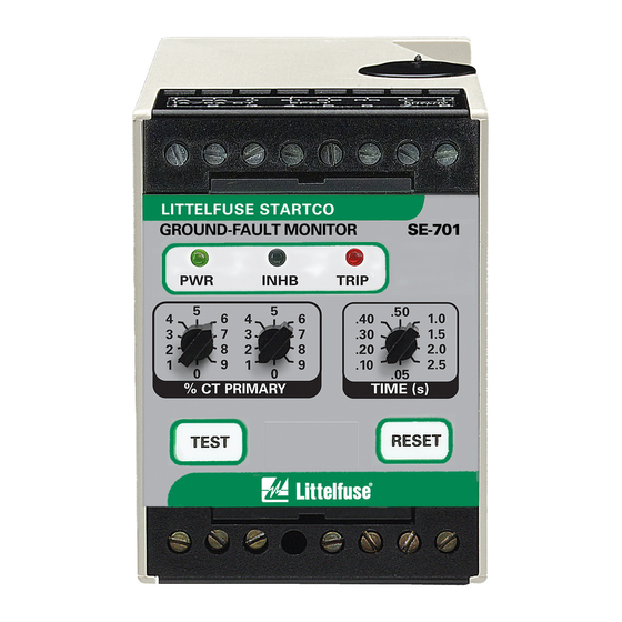
Page 6: Front-Panel Controls
ROUND AULT The SE-701 has a definite-time trip characteristic. The in the OFF position. TIME (s) selector switch is used to set the ground-fault trip delay time for coordination with upstream and 2.4 A... -
Page 7: Se-701 Outline And Mounting Details
N L 1 3. OVERALL DIMENSION WHEN MOUNTED ON DIN EN50022 35 mm x 7.5 mm TOP-HAT RAIL. 4. ADJUSTMENT KNOBS ARE REMOVABLE. CONFIGURATION SWITCHES SHOWN IN DEFAULT POSITION. BOTTOM FIGURE 1. SE-701 Outline and Mounting Details. Pub. SE-701-M, January 18, 2008. -
Page 8: Se-701 Compatibility
FIGURE 2. Typical Connection Diagram. 4. SE-701 C OMPATIBILITY The current SE-701 has been enhanced with the addition of non-volatile trip memory for the fail-safe relay operating mode. Prior to hardware revision 07, a mechanical flag was used instead of non-volatile trip memory. -
Page 9: Efct-1 Sensitive Earth-Fault Ct
1.0 (0.04) DEEP (OPTIONAL) 110.0 56.0 (2.21) (0.22) (4.33) (0.22) FRONT SIDE NOTES: DIMENSIONS IN MILLIMETRES (INCHES). MOUNTING SCREWS: M4 OR 8-32. PRESS MOUNTING FEET IN PLACE USING INSTALLATION TOOL PROVIDED. FIGURE 3. EFCT-1 Sensitive Earth-Fault CT. Pub. SE-701-M, January 18, 2008. -
Page 10: Efct-2 Sensitive Earth-Fault Ct
31.0 25.0 (1.22) (0.98) FLUX CONDITIONER 5.0 (0.20) DIA (INCLUDED) BONDING SCREW 198.0 (0.33) (7.80) (0.33) FRONT SIDE NOTES: 1. DIMENSIONS IN MILLIMETRES (INCHES). MOUNTING SCREWS: M5 OR 10-32. FIGURE 4. EFCT-2 Sensitive Earth-Fault CT. Pub. SE-701-M, January 18, 2008. -
Page 11: Efct-26 Sensitive Earth-Fault Ct
FRONT SIDE NOTES: MOUNTING FOOT INSTALLATION DIMENSIONS IN MILLIMETRES (INCHES). TOOL PRESS MOUNTING FEET IN PLACE USING INSTALLATION TOOL PROVIDED (DETAIL ‘A’) MOUNTING SCREWS: M4 OR 8-32. DETAIL ‘A’ FIGURE 5. EFCT-26 Sensitive Earth-Fault CT. Pub. SE-701-M, January 18, 2008. -
Page 12: Pma-55 Panel-Mount Adapter
8.7 (0.34) DIA LOCKNUTS PROVIDED. CONNECT WIRING TO TERMINALS. 4.3 (0.17) RAD ALTERNATE INSTALL BEZEL USING 6-32 x 0.31 SCREWS CONFIGURATIONS PROVIDED. NOTE: 1. DIMENSIONS IN MILLIMETRES (INCHES). PANEL CUTOUT DETAIL FIGURE 6. PMA-55 Panel-Mount Adapter. Pub. SE-701-M, January 18, 2008. -
Page 13: Pma-60 Panel-Mount Adapter
AND LOCKNUTS PROVIDED. 4.3 (0.17) RAD CONNECT WIRING TO TERMINALS. ALTERNATE ATTACH COVER USING THUMB SCREWS CONFIGURATIONS PROVIDED. NOTE: 1. DIMENSIONS IN MILLIMETRES (INCHES). 2. MEETS NEMA 3, IP53. PANEL CUTOUT DETAIL FIGURE 7. PMA-60 Panel-Mount Adapter Pub. SE-701-M, January 18, 2008. -
Page 14: Technical Specifications
CT..........1- or 5-A Secondary Environment: Rating, or EFCT-x Operating Temperature ..-40 to 60°C CT Detection ....Open-Circuit Detection Storage Temperature ..-55 to 80°C with EFCT-x Humidity ......85% Non-Condensing Surge Withstand......ANSI/IEEE 37.90.1-1989 (Oscillatory and Fast Transient) Pub. SE-701-M, January 18, 2008. -
Page 15: Ordering Information
RFI Compliance ..... FCC Part 15, Subpart B, repair, replace, or refund the original purchase price of an Class A – Unintentional SE-701 that is determined by Startco to be defective if it Radiators is returned to the Startco factory, freight prepaid, within the warranty period. -
Page 16: Ground-Fault Performance Test
0.1 to 9.9 seconds. Set the test current to 120% of REMOTE SE-100T the SE-701 setting. Fig. 8 (b) shows a test circuit TEST using a Startco SE-100T Ground-Fault-Relay Tester. The SE-100T provides a test current of 0.65 or 2.75 A for testing 0.5- and 2.0-A trip levels.
Need help?
Do you have a question about the SE-701 and is the answer not in the manual?
Questions and answers