Table of Contents
Advertisement
Quick Links
Publication: SE-703-M
Document: S95-C703-00000
Printed in Canada.
SE-703 MANUAL
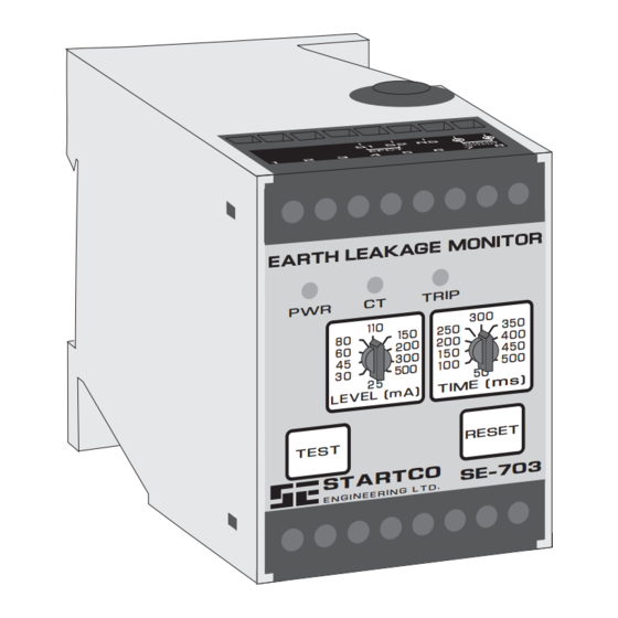
EARTH-LEAKAGE MONITOR
MARCH 4, 2008
REVISION 6
E A R T H
E A R T H
P W R
Copyright © 2008 by Startco Engineering Ltd.
All rights reserved.
M O N IT O R
M O N IT O R
L E A K A G E
L E A K A G E
T R IP
C T
3 0 0
3 5 0
11 0
2 5 0
15 0
4 0 0
8 0
2 0 0
2 0 0
4 5 0
6 0
1 5 0
3 0 0
5 0 0
4 5
1 0 0
5 0 0
5 0
3 0
m s
T IM E (
2 5
L E V E L (m A )
R E S E T
T E S T
S E - 7 0 3
C O
S T A R T
.
R I N G L T D
E N G I N E E
)
Advertisement
Table of Contents

Summary of Contents for Startco SE-703
- Page 1 S E - 7 0 3 S T A R T R I N G L T D E N G I N E E Copyright © 2008 by Startco Engineering Ltd. All rights reserved. Publication: SE-703-M Document: S95-C703-00000 Printed in Canada.
- Page 2 This page intentionally left blank.
-
Page 3: Table Of Contents
ISCLAIMER Technical Specifications ...........10 Specifications are subject to change without notice. Ordering Information ..........11 Startco Engineering Ltd. is not liable for contingent or consequential damages, or for expenses sustained as a Warranty..............11 result of incorrect application, incorrect adjustment, or a malfunction. - Page 4 Startco Engineering Ltd. Page ii SE-703 Earth-Leakage Monitor Rev. 0 This page intentionally left blank Pub. SE-703-M, March 4, 2008.
-
Page 5: General
In the fail-safe mode, non-volatile memory retains the The TEST switch is used to test the earth-leakage trip status of the SE-703. If tripped, and the supply circuit, the indication, and the output relay. When the voltage is cycled, the SE-703 will remain tripped, with... -
Page 6: Se-703 Outline And Mounting Details
3. OVERALL DIMENSION WHEN MOUNTED ON DIN EN50022 35 mm x 7.5 mm TOP-HAT RAIL. 4. ADJUSTMENT KNOBS ARE REMOVABLE. 5. CONFIGURATION SWITCHES SHOWN IN DEFAULT BOTTOM POSITION. FIGURE 1. SE-703 Outline and Mounting Details. Pub. SE-703-M, March 4, 2008. -
Page 7: Analog Output
SE-703 Earth-Leakage Monitor and an EFCT-series when earth-leakage current is 500 mA. current sensor connected as shown in Fig. 2. An SE-703 can be surface or DIN-rail mounted. See 2.5 S IAGNOSTICS Fig. 1. Panel mounting requires a PMA-55 or PMA-60 A diagnostic trip is indicated by two fast flashes of the Panel-Mount Adapter. -
Page 8: Se-703 Compatibility
Prior to hardware revision 04, a mechanical flag was used instead of non-volatile trip memory. The current revision of the SE-703 can directly replace previous revision units. The hardware-revision number is listed on the SE-703 model/serial-number label affixed to the SE-703 enclosure. Both generations of SE-703 are compared in Table 1. -
Page 9: Efct-1 Outline And Mounting Details
EFCT-1FC FLUX 8-mm HEX NUT CONDITIONER 1.0 (0.04) DEEP (OPTIONAL) 110.0 56.0 (2.21) (0.22) (4.33) (0.22) FRONT SIDE NOTES: DIMENSIONS IN MILLIMETRES (INCHES). MOUNTING SCREWS: M4 OR 8-32. FIGURE 3. EFCT-1 Outline and Mounting Details. Pub. SE-703-M, March 4, 2008. -
Page 10: Efct-2 Outline And Mounting Details
25.0 (1.22) (0.98) FLUX CONDITIONER (INCLUDED) 5.0 (0.20) DIA BONDING SCREW 198.0 (0.33) (7.80) (0.33) FRONT SIDE NOTES: 1. DIMENSIONS IN MILLIMETRES (INCHES). MOUNTING SCREWS: M5 OR 10-32. FIGURE 4. EFCT-2 Outline and Mounting Details. Pub. SE-703-M, March 4, 2008. -
Page 11: Efct-26 Outline And Mounting Details
SIDE NOTES: MOUNTING FOOT INSTALLATION DIMENSIONS IN MILLIMETRES (INCHES). TOOL PRESS MOUNTING FEET IN PLACE USING INSTALLATION TOOL PROVIDED (DETAIL ‘A’) MOUNTING SCREWS: M4 OR 8-32. DETAIL ‘A’ FIGURE 5. EFCT-26 Outline and Mounting Details. Pub. SE-703-M, March 4, 2008. -
Page 12: Pma-55 Panel-Mount Adapter
8.7 (0.34) DIA AND LOCKNUTS PROVIDED. 4.3 (0.17) RAD CONNECT WIRING TO TERMINALS. ALTERNATE INSTALL BEZEL USING 6-32 x 0.31 SCREWS CONFIGURATIONS PROVIDED. NOTE: 1. DIMENSIONS IN MILLIMETRES (INCHES) PANEL CUTOUT DETAIL FIGURE 6. PMA-55 Panel-Mount Adapter Pub. SE-703-M, March 4, 2008. -
Page 13: Pma-60 Panel-Mount Adapter
AND LOCKNUTS PROVIDED. 4.3 (0.17) RAD CONNECT WIRING TO TERMINALS. ALTERNATE ATTACH COVER USING THUMB SCREWS CONFIGURATIONS PROVIDED. NOTE: 1. DIMENSIONS IN MILLIMETRES (INCHES). 2. MEETS IP53, NEMA3 . PANEL CUTOUT DETAIL FIGURE 7. PMA-60 Panel-Mount Adapter Pub. SE-703-M, March 4, 2008. -
Page 14: Technical Specifications
Radiated RF.......IEC 61000-4-3, EN 61000-4-3 Functional Test ......Front-Panel Switch 10 V/m, 80-1000 MHz, 80% AM (1 kHz). 10 V/m, 900 MHz, 200 Hz Pulse Modulated Fast Transient ....IEC 61000-4-4, EN 61000-4-4 ±2 kV Common Mode ±1 kV Differential Mode Pub. SE-703-M, March 4, 2008. -
Page 15: Ordering Information
At 50 or 60 Hz. an SE-703 that is determined by Startco to be defective if Maximum lead resistance of 2 Ω. it is returned to the Startco factory, freight prepaid, Trip Time at 1.5 x trip-level setting. -
Page 16: Performance Test
Fig. 8 shows the use of resistors that reduce the ESULTS injected current to 10% of the SE-400 setting. Set the test current to 120% of the SE-703 setting. Inject the test current through the current-transformer window for at least 2.5 seconds. Verify that the circuit under test has reacted properly.


Need help?
Do you have a question about the SE-703 and is the answer not in the manual?
Questions and answers