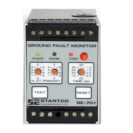
Summary of Contents for Startco SE-701
- Page 1 SE-701 MANUAL GROUND-FAULT MONITOR DECEMBER 19, 2000 REVISION 4 Copyright © 2000 by Startco Engineering Ltd. All rights reserved. Publication: SE-701-M Document: S95-C701-00000 Printed in Canada.
- Page 2 Blank Page...
-
Page 3: Table Of Contents
Front-Panel Controls..........1 ISCLAIMER 2.2.1 Ground-Fault Trip Level ........1 2.2.2 Ground-Fault Trip Time.........1 Specifications are subject to change without notice. Startco 2.2.3 Reset ...............1 Engineering Ltd. is not liable for contingent or 2.2.4 Test ..............3 consequential damages, or for expenses sustained as a result Front-Panel Indication ..........3... - Page 4 Blank Page...
-
Page 5: General
ELAY PERATING protection. For reliable ground-fault detection, the ground- The SE-701 has one output relay with isolated normally fault trip level must be substantially below the prospective open and normally closed contacts. Switch 1 is used to set ground-fault current. To avoid sympathetic tripping, the the operating mode of the output relay. - Page 6 Startco Engineering Ltd. Page 2 SE-701 Ground-Fault Monitor Rev. 4 FIGURE 1. SE-701 Outline and Mounting Details. Pub. SE-701-M, December 19, 2000.
-
Page 7: Test
If Switch 5 is in the AUTORESET position and the remote-reset terminals are shorted, operation is the same as Supply: for older SE-701’s with the A1 or A2 option. 01 Option......120 Vac (+15%, -40%), 50/60 Hz, 2.5 VA 2.2.4 T 02 Option......240 Vac (+15%, -40%),... - Page 8 Startco Engineering Ltd. Page 4 SE-701 Ground-Fault Monitor Rev. 4 FIGURE 2. Typical Connection Diagram. Pub. SE-701-M, December 19, 2000.
-
Page 9: Ordering Information
EFCT-2FC ..Flux Conditioner, 139 mm (5.5”) Window Make/Carry 0.2 s ....20 A Carry Continuous....8 A PMA-55 ...Panel-Mount Adapter Break: dc .........30 W Resistive, SE-EFVC..Voltage Clamp 15 W Inductive (L/R = 0.4 s) Consult factory for custom mounting adapters. Pub. SE-701-M, December 19, 2000. - Page 10 Startco Engineering Ltd. Page 6 SE-701 Ground-Fault Monitor Rev. 4 FIGURE 3. EFCT-1 Outline and Mounting Details. Pub. SE-701-M, December 19, 2000.
- Page 11 Startco Engineering Ltd. Page 7 SE-701 Ground-Fault Monitor Rev. 4 FIGURE 4. EFCT-2 Outline and Mounting Details. Pub. SE-701-M, December 19, 2000.
- Page 12 Startco Engineering Ltd. Page 8 SE-701 Ground-Fault Monitor Rev. 2 FIGURE 5. PMA-55 Panel-Mount Adapter. Pub. SE-701-M, December 19, 2000.


Need help?
Do you have a question about the SE-701 and is the answer not in the manual?
Questions and answers