Table of Contents
Advertisement
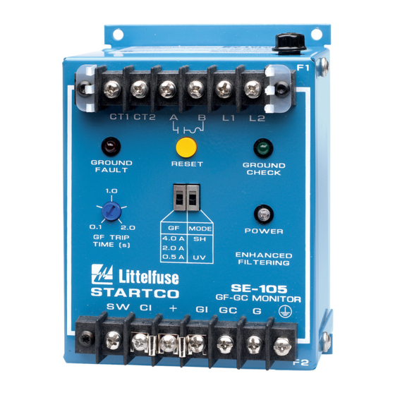
GROUND-FAULT GROUND-CHECK MONITOR
Publication: SE-105-M
Document: S95-C105-00000
Printed in Canada.
SE-105 MANUAL
NOVEMBER 24, 2005
REVISION 9
C T 1 C T 2 A
G R O U N D
F A U L T
1 . 0
G F
0 . 1
2 . 0
G F T R I P
4 . 0 A
T I M E ( s )
2 . 0 A
0 . 5 A
S T A R T C O
E N G I N E E R I N G L T D .
S W
C I
Copyright
2005 by Startco Engineering Ltd.
All rights reserved.
F 1
B
L 1
L 2
R E S E T
G R O U N D
C H E C K
P O W E R
M O D E
S H
U V
S E - 1 0 5
GF-GC MONITOR
G I
G C
G
F 2
Advertisement
Table of Contents

Related Manuals for Startco SE-105


Summary of Contents for Startco SE-105
- Page 1 S E - 1 0 5 GF-GC MONITOR E N G I N E E R I N G L T D . Copyright 2005 by Startco Engineering Ltd. All rights reserved. Publication: SE-105-M Document: S95-C105-00000 Printed in Canada.
-
Page 2: Table Of Contents
Compatibility ............4 Technical Specifications ........11 Specifications are subject to change without notice. Startco Engineering Ltd. is not liable for contingent or Ordering Information ......... 12 consequential damages, or for expenses sustained as a result of incorrect application, incorrect adjustment, or a Warranty .............. -
Page 3: Gf Trip Time
For the latching ground-check option, the GROUND- CHECK LED is red and it indicates a latched ground- : The SE-105 is not a lock-out device. Follow check trip. AUTION lock-out procedures for maintenance. -
Page 4: Ground-Check Termination
RESET SWITCH K1 CLOSES ON GROUND-CHECK VALID, 24-120 Vac/Vdc DO NOT USE K1 IN A TRIP CIRCUIT. ALTERNATE K2 CLOSES ON GROUND-FAULT TRIP. RESET CIRCUIT RK-13 CONNECTION WITH REMOTE INDICATION AND RESET FIGURE 1. Typical Application. Pub. SE-105-M, November 24, 2005. -
Page 5: Se-105
1. DIMENSIONS IN MILLIMETRES (INCHES). NOTE 5 2. TERMINAL-BLOCK SCREWS: 6-32 x 0.25. 3. MOUNTING SCREWS: M4 OR 8-32. 4. SHOWN WITH TERMINAL-BLOCK COVER REMOVED. 5. MINIMUM CLEARANCE FOR FUSE REMOVAL. FIGURE 2. SE-105 Outline and Mounting Details. Pub. SE-105-M, November 24, 2005. -
Page 6: Ground-Fault Ct
SE-105 terminals CT1 and CT2. The CT connection to Use CT-primary current injection to test the ground- the SE-105 is not polarity sensitive. Ground one side of fault circuit. Fig. 12 shows test circuits using the Startco the CT secondary. - Page 7 MOUNTING DETAIL BOTTOM DIMENSIONS PART NUMBER 55.9 (2.20) 120.7 (4.75) 101.6 (4.00) 98.3 (3.87) 108.0 (4.25) 5.6 (0.22) CT200 88.9 (3.50) 154.0 (6.06) 133.4 (5.25) 139.7 (5.50) 144.5 (5.69) 7.1 (0.28) CT200L FIGURE 3. Current Transformers. Pub. SE-105-M, November 24, 2005.
-
Page 8: Zener-Diode Termination Devices
1. DIMENSIONS IN MILLIMETRES (INCHES). 2. TERMINAL-BLOCK SCREWS: 6-32 x 0.25. 3. MOUNTING SCREWS: M4 OR 8-32. 4. ENCLOSURE IS ELECTRICALLY CONNECTED TO TERMINAL G. 5. MAY BE IMMERSED IN GLYCOL. FIGURE 5. SE-TA6 Termination Assembly. Pub. SE-105-M, November 24, 2005. -
Page 9: Rk-102 Remote Indication And Reset
E N G I N E E R I N G L T D . R K - 1 0 5 3.8 (0.15) 22.25 (0.875) SIDE VIEW MOUNTING DETAIL FRONT VIEW NOTES: 1. DIMENSIONS IN MILLIMETRES (INCHES). 2. NEMA 1. FIGURE 7. RK-105 Remote Indication-and-Reset Assembly. Pub. SE-105-M, November 24, 2005. -
Page 10: Rk-105I Remote Indication Assembly
1. DIMENSIONS IN MILLIMETRES (INCHES). 2. NEMA 1. FIGURE 8. RK-105I Remote Indication Assembly. CI/GI GI/RI SIDE VIEW RK-13 SHOWN MOUNTED ON SE-105 60.2 (2.37) INSTALLATION INSTRUCTIONS: 1. REMOVE FOUR LEFTMOST LOWER TERMINAL BLOCK SCREWS. 2. PLACE RK-13 ON TERMINAL BLOCK AND REPLACE SCREWS. -
Page 11: Ppi-600V Parallel-Path Isolator
Startco Engineering Ltd. Page 9 SE-105 Ground-Fault Ground-Check Monitor Rev. 8 FIGURE 10. PPI-600V Parallel-Path Isolator. Pub. SE-105-M, November 24, 2005. -
Page 12: Ppi-600V Typical Installation
Startco Engineering Ltd. Page 10 SE-105 Ground-Fault Ground-Check Monitor Rev. 9 GROUND CHECK MONITOR SE-105, SE-107, SE-134, OR SE-135 CABLE GROUND GROUND CHECK OUTGOING GROUND CHECK OUTGOING GROUND INCOMING GROUND CHASSIS GROUND BUS PPI-600V NOTES: 1. THE PARALLEL-PATH ISOLATOR IS NOT POLARIZED. EITHER FLANGE CAN BE CONNECTED TO CHASSIS. -
Page 13: Technical Specifications
Nominal Loop Current ..25 mA Induced-ac Withstand ..25 Vac Continuous, Australia 120 Vac for 3 s Fuse Rating (F2)....0.5 A, 250 Vac, Time Delay Fuse Part Number....Bussman MDA-1/2, MDL-1/2 or Littelfuse 313.500 Pub. SE-105-M, November 24, 2005. -
Page 14: Ordering Information
D 120-Vac/dc Supply SE-105 that is determined by Startco to be defective if it Each SE-105 is supplied with a 1N5339B termination device. is returned to the Startco factory, freight prepaid, within List options required in order shown above. -
Page 15: Ground-Fault Performance Test
0.5 to 9.9 A for a duration of 0.1 to 9.9 seconds. Set the test current to 0.6, 2.3, or 4.6 A for SE-105 units set at 0.5, 2.0, or 4.0 A respectively. Fig. 12b shows a test circuit using a FIGURE 12.
Need help?
Do you have a question about the SE-105 and is the answer not in the manual?
Questions and answers