
Related Manuals for Startco SE-601


Summary of Contents for Startco SE-601
- Page 1 SE-601 MANUAL DC GROUND-FAULT MONITOR JULY 4, 2002 REVISION 0 Copyright © 2002 by Startco Engineering Ltd. All rights reserved. Publication: SE-601-M Document: S95-C601-00000 Printed in Canada.
- Page 2 Blank Page...
-
Page 3: Table Of Contents
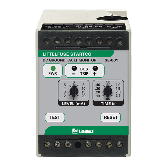
2.1.2 Autoreset............1 IST OF ABLES 2.2 Front-Panel Controls ............1 ABLE 2.2.1 Trip Level ............1 2.2.2 Trip Time............1 SE-601 Trip Levels and Fault Values ......1 2.2.3 Reset ...............1 2.2.4 Test ..............1 2.3 Front-Panel Indication..........1 ISCLAIMER 2.3.1 Power ..............1 2.3.2 Trip ..............1 Specifications are subject to change without notice. - Page 4 Blank Page...
-
Page 5: General
The relay contacts signal. The front-panel RESET switch is disabled when (terminals 13, 14, 15, and 16) are shown with the SE-601 remote-reset terminals 6 and 7 are shorted. de-energized. Switch 1 is used to set the operating mode of If Switch 2 is in the LATCHING position, a trip remains the output relay. -
Page 6: Se-601 Outline And Mounting Details
Startco Engineering Ltd. Page 2 SE-601 DC Ground-Fault Monitor Rev. 0 FIGURE 1. SE-601 Outline and Mounting Details. Pub. SE-601-M, July 4, 2002. -
Page 7: Analog Output
3. I NSTALLATION Trip-Level Settings ....1, 2, 3, 4, 5, 6, 8, 10, 15, Connect the SE-601 DC Ground-Fault Monitor and and 20 mA SE-GRM Ground-Reference Module as shown in Fig. 2. Remove the connection to terminals 5 and 9 for Trip-Time Settings..... -
Page 8: 4.2 Se-Grm
SE-GRM048..Ground-Reference Module for 48-Vdc Transient) system. SE-GRM125..Ground-Reference Module for 125-Vdc system. SE-GRM250..Ground-Reference Module for 250-Vdc system. Consult factory for other ground-reference modules. PMA-55 ..Panel-Mount Adapter (See Fig. 4) Consult factory for custom mounting adapters. Pub. SE-601-M, July 4, 2002. - Page 9 Startco Engineering Ltd. Page 5 SE-601 DC Ground-Fault Monitor Rev. 0 FIGURE 3. SE-GRM Ground-Reference Module. Pub. SE-601-M, July 4, 2002.
-
Page 10: Pma-55 Panel-Mount Adapter
Startco Engineering Ltd. Page 6 SE-601 DC Ground-Fault Monitor Rev. 0 FIGURE 4. PMA-55 Panel-Mount Adapter. Pub. SE-601-M, July 4, 2002.
Need help?
Do you have a question about the SE-601 and is the answer not in the manual?
Questions and answers