Table of Contents
Advertisement
Quick Links
Advertisement
Table of Contents

Subscribe to Our Youtube Channel
Related Manuals for NXP Semiconductors JN516x-EK001


Summary of Contents for NXP Semiconductors JN516x-EK001
- Page 1 JN516x-EK001 Evaluation Kit User Guide JN-UG-3093 Revision 1.5 11 February 2015...
- Page 2 JN516x-EK001 Evaluation Kit User Guide © NXP Laboratories UK 2015 JN-UG-3093 v1.5...
-
Page 3: Table Of Contents
JN516x-EK001 Evaluation Kit User Guide Contents Preface Organisation Conventions Acronyms and Abbreviations Related Documents Support Resources Trademarks 1. Introduction to the Evaluation Kit 1.1 Typical Networks 1.2 Kit Contents 1.2.1 Kit Containing Raspberry Pi 1.2.2 Kit Containing Linksys Router 1.2.3 Supplied Board Configuratons 1.3 Kit Hardware... - Page 4 Contents 3. Smart Home Demonstration 3.1 Demo System Overview 3.2 Connecting Up the Border-Router 3.2.1 Raspberry Pi Connection Instructions 3.2.2 Linksys Router Connection Instructions 3.3 Setting Up and Operating the Demo System 4. Where Next? 4.1 Which Protocol? 4.2 Software Developer’s Kit (SDK) 4.2.1 Toolchain (JN-SW-4041 or JN-SW-4141) 4.2.2 IEEE 802.15.4 SDK (JN-SW-4163) 4.2.3 JenNet-IP SDK (JN-SW-4165)
- Page 5 JN516x-EK001 Evaluation Kit User Guide Appendices A. Remote Control Operations in the Demonstration B. Firmware Re-programming B.1 Re-programming Remote Control Unit B.2 Re-programming JN5168 Modules B.3 Re-programming JN5168 USB Dongles B.4 Installing the FTDI Device Driver for USB Connections C. Compliance Statements and Documentation C.1 FCC Statements and Documentation...
- Page 6 Contents © NXP Laboratories UK 2015 JN-UG-3093 v1.5...
-
Page 7: Preface
JN516x-EK001 Evaluation Kit User Guide Preface This manual provides an introduction to the NXP JN516x-EK001 Evaluation Kit, based around the JN516x family of wireless microcontrollers. The manual also describes how to run the pre-loaded Smart Home Demonstration using components from the kit. -
Page 8: Acronyms And Abbreviations
About this Manual This is a Caution. It warns of situations that may result in equipment malfunction or damage. Acronyms and Abbreviations Application Programming Interface Internet Protocol JenNet Jennic Network layer protocol Local Area Network Pulse Width Modulation Software Developer’s Kit Wide Area Network WPAN Wireless Personal Area Network... -
Page 9: Introduction To The Evaluation Kit
User Guide 1. Introduction to the Evaluation Kit Welcome to the JN516x-EK001 Evaluation Kit, which is based around the NXP JN516x family of wireless microcontrollers. A Smart Home Demonstration is pre- loaded into certain kit components, allowing a small wireless network with IP connectivity to be quickly assembled and used. -
Page 10: Typical Networks
Introduction to the Evaluation Kit 1.1 Typical Networks The JN516x-EK001 Evaluation Kit can be used as a platform for developing a wide range of wireless network applications, where these applications run on JN516x devices embedded in the network nodes. Example networks are: ... -
Page 11: Kit Contents
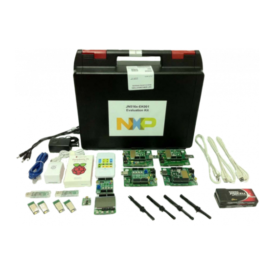
User Guide 1.2 Kit Contents The JN516x-EK001 Evaluation Kit contains the hardware components required to assemble a wireless network which may be connected to an IP-based network (such as the Internet). The principal network components included in the kit are: ... - Page 12 JN5168 modules. Details of the supplied combinations are provided in Section 1.2.3. Note: A JN5168-001-T0y component comprises a JN5168-001-M0y module mounted on a (short) Mezzanine Board of the type DR1179. It is labelled JN5168-001-M0y. Figure 4: JN516x-EK001 Evaluation Kit (Raspberry Pi Edition) © NXP Laboratories UK 2015 JN-UG-3093 v1.5...
-
Page 13: Kit Containing Linksys Router
JN516x-EK001 Evaluation Kit User Guide 1.2.2 Kit Containing Linksys Router In this kit, you will find the following components (numbers refer to Figure 1. Linksys Wireless-N Broadband Router (WRT160NL) 2. 12V DC power supply unit (universal type) for Linksys router or Carrier Boards 3. -
Page 14: Supplied Board Configuratons
Chapter 1 Introduction to the Evaluation Kit Figure 5: JN516x-EK001 Evaluation Kit (Linksys Edition) 1.2.3 Supplied Board Configuratons The Carrier Boards of the JN516x-E001 Evaluation are supplied pre-fitted with JN5168 modules and Expansion Boards. Table 1 below details the supplied combinations of module type and expansion board type. -
Page 15: Kit Hardware
The Raspberry Pi board and Linksys router are pre-programmed with NXP firmware. 1.3 Kit Hardware This section details the hardware devices supplied in the JN516x-EK001 Evaluation Kit (see Section 1.2 for full kit contents): ... -
Page 16: Carrier Boards (Dr1174)
Chapter 1 Introduction to the Evaluation Kit Figure 6: DR1159 Remote Control Unit (and DR1128 Programming Dongle) 1.3.2 Carrier Boards (DR1174) The four carrier boards (part number: DR1174) are physically identical. They are all pre-fitted with an Arduino-compatible expansion board and a JN5168-based module, but they are not all fitted with the same types of expansion board and module - the hardware configurations of the four Carrier Boards are detailed in Table 1 on page... - Page 17 JN516x-EK001 Evaluation Kit User Guide Each Carrier Board has the following features (also refer to Figure 7 Figure JN51xx module site Arduino-compatible header (in four parts) 10-way JTAG debug header PCB pads for 40-way expansion header ...
- Page 18 Chapter 1 Introduction to the Evaluation Kit Figure 8: DR1174 Carrier Board (with a JN516x Module) Note the following: The expansion board is an Arduino-compatible shield attached to the Arduino- compatible header. The JN5168-based module which is pre-fitted to the module site has been pre- loaded with the JenNet-IP Smart Home demonstration.
-
Page 19: Power Source Selection
JN516x-EK001 Evaluation Kit User Guide 1.3.2.1 Power Source Selection The board can be used in normal-power mode or low-power mode, selected using the J4 and Low PWR jumpers. For the locations of these jumpers, refer to Figure Note: The Low PWR jumper is hidden under the... - Page 20 Chapter 1 Introduction to the Evaluation Kit Normal-Power Mode In normal-power mode, the board can be powered from one of the following: 4 AAA batteries, connected on the underside of the board External 7-12V DC supply via 2.1-mm connector ...
-
Page 21: Pre-Assembled Boards
JN516x-EK001 Evaluation Kit User Guide Normal-power Low-power mode mode Figure 11: Lower-Power Mode Selection (using Low PWR Jumper) 1.3.2.2 Pre-assembled Boards As indicated above, each Carrier Board is supplied pre-fitted with a JN5168 module and an expansion board. Figure 12 below shows a pre-assembled board carrying a module with integrated antenna. -
Page 22: Lighting/Sensor Expansion Boards (Dr1175)
Chapter 1 Introduction to the Evaluation Kit 1.3.3 Lighting/Sensor Expansion Boards (DR1175) The three Lighting/Sensor Expansion Boards (part number: DR1175) are physically identical. They are Arduino-compatible shields that are supplied pre-fitted to the Arduino-compatible headers of three of the Carrier Boards (see Section 1.3.2). - Page 23 JN516x-EK001 Evaluation Kit User Guide Figure 14: DR1175 Lighting/Sensor Expansion Board Caution: The LEDs on the Lighting/Sensor Expansion Board are very bright at maximum intensity. To avoid damage to your eyes, do not look into them directly for an extended period of time.
-
Page 24: Generic Expansion Boards (Dr1199)
Chapter 1 Introduction to the Evaluation Kit 1.3.4 Generic Expansion Boards (DR1199) The two Generic Expansion Boards (part number: DR1199) are physically identical. They are Arduino-compatible shields and one is pre-fitted to the Arduino-compatible header on a Carrier Board. Note: For full details of the board, refer to the Carrier and Expansion Boards Reference Manual (JN-RM- 2063), available from the NXP Wireless Connectivity TechZone (see... - Page 25 JN516x-EK001 Evaluation Kit User Guide FTDI GPIO Chip Port Potentiometer Figure 15: DR1199 Generic Expansion Board Layout Figure 16: DR1199 Generic Expansion Board JN-UG-3093 v1.5 © NXP Laboratories UK 2015...
-
Page 26: Lcd Expansion Board (Dr1215)
Chapter 1 Introduction to the Evaluation Kit 1.3.5 LCD Expansion Board (DR1215) The LCD Expansion Board (part number: DR1215) is supplied for applications that need to provide on-screen feedback to the user. It is an Arduino-compatible shield but is not pre-fitted to a Carrier Board. Note 1: For full details of the board, refer to the Carrier and Expansion Boards Reference Manual (JN-RM- 2063), available from the NXP Wireless Connectivity... -
Page 27: Jn5168 Modules (Jn5168-001-T0Y)
JN516x-EK001 Evaluation Kit User Guide Figure 18: DR1215 LCD Expansion Board 1.3.6 JN5168 Modules (JN5168-001-T0y) Four types of JN5168-based module are supplied in the kit. Each type is a JN5168-001-M0y module mounted on a (short) Mezzanine Board (DR1179), the part number of the combined component being JN5168-001-T0y. - Page 28 Chapter 1 Introduction to the Evaluation Kit a larger radio transmission range. A uFL connector is used to connect the module to an antenna on the Carrier Board via a flying lead (see below). Caution: The JN5168-001-TO6 high-power module is intended only for use in the North American (FCC and IC) markets.
-
Page 29: Antenna Mounting And Connection
JN516x-EK001 Evaluation Kit User Guide 1.3.6.1 Antenna Mounting and Connection The JN5168 modules with uFL connectors must be used with the supplied antennas. An antenna is provided with a 7-cm fly lead attached, which allows the antenna to be connected to the module. To mount and connect an antenna, proceed as follows (also... -
Page 30: Usb Dongles (Dr1198)
Chapter 1 Introduction to the Evaluation Kit Antenna Locating Lugs Site Antenna Base Piece DIO8 Module Connector Figure 21: Antenna Mounting and Connection 1.3.7 USB Dongles (DR1198) Two JN5168 USB Dongles (part number: DR1198) are supplied in the kit. One is intended for use in the JenNet-IP Smart Home Demonstration and the other can be employed in some other capacity, such as packet sniffing (see below). -
Page 31: Border-Router
JN516x-EK001 Evaluation Kit User Guide The two dongles are pre-programmed with identical software for the JenNet-IP Smart Home Demonstration. This software allows either dongle to be plugged into a USB port of either the Raspberry Pi board or Linksys router (see Section 1.3.8) to form a... - Page 32 Chapter 1 Introduction to the Evaluation Kit The IP (LAN/WAN) side of the system can be one of: Wired IP or Ethernet bus (possibly connected to the Internet) Wi-Fi network (possibly connected to the Internet) The possible Border-Router implementations are illustrated in Figure 23 below.
-
Page 33: Raspberry Pi
JN516x-EK001 Evaluation Kit User Guide 1.3.8.1 Raspberry Pi The Raspberry Pi single-board computer (Model B+) is supplied with accessories consisting of: Dedicated 5V DC power supply unit (universal type) microSD card (pre-installed) RJ45 Ethernet cable The board and its accessories are shown in... -
Page 34: Linksys Router
Chapter 1 Introduction to the Evaluation Kit 1.3.8.2 Linksys Router The Linksys Wireless-N Broadband Router (WRT160NL) is supplied in the older kits and comes with accessories consisting of: 12V DC power supply unit (universal type) 2 antennas with SMA connectors ... -
Page 35: Smart Home Demonstration
JN516x-EK001 Evaluation Kit User Guide 1.4 Smart Home Demonstration Certain components of the kit are pre-loaded with the software for the JenNet-IP Smart Home Demonstration. Running this demonstration will allow you to test most components of the kit (even if you do not intend to use the JenNet-IP protocol to develop your own applications). - Page 36 Chapter 1 Introduction to the Evaluation Kit © NXP Laboratories UK 2015 JN-UG-3093 v1.5...
-
Page 37: Wireless Network Concepts
The concepts covered are relevant to all the wireless network protocols supported by the JN516x-EK001 Evaluation Kit - that is, JenNet-IP, ZigBee PRO and ZigBee RF4CE. Note that all of these protocols are built on IEEE 802.15.4, which is also supported on its own. -
Page 38: Node Types
Chapter 2 Wireless Network Concepts 2.2 Node Types In addition to running an application (e.g. temperature measurement), each node of a wireless network has a networking role. Most IEEE 802.15.4-based networks can contain three types of node, differentiated by their networking roles, as described below (ZigBee RF4CE is an exception): Node Type Description... -
Page 39: Network Formation And Topology
JN516x-EK001 Evaluation Kit User Guide 2.4 Network Formation and Topology A wireless network is formed as follows: 1. The first node to be started is the Co-ordinator, which performs network initialisation including the selection of the radio channel in which the network... -
Page 40: Tree Networks
Chapter 2 Wireless Network Concepts 2.4.2 Tree Networks A Tree network may contain the full range of node types - Co-ordinator, Routers and End Devices - with the Co-ordinator at the top of the (inverted) tree. Any node can only communicate directly with its parent and children (if any). -
Page 41: Wireless Network Protocol Stack
Flash memory of the node. In order to use the JenNet-IP Smart Home Demonstration which is pre-loaded in the JN516x-EK001 Evaluation Kit boards, no knowledge of the JenNet-IP software is required. However, you should familiarise yourself with the software for your chosen protocol before starting your own application development - refer to Section 4.3... - Page 42 Chapter 2 Wireless Network Concepts © NXP Laboratories UK 2015 JN-UG-3093 v1.5...
-
Page 43: Smart Home Demonstration
User Guide 3. Smart Home Demonstration The chapter describes how to use the contents of the JN516x-EK001 Evaluation Kit to set up and run the pre-loaded JenNet-IP Smart Home Demonstration. Note 1: The procedures in this chapter provide a ‘quick start’... - Page 44 Chapter 3 Smart Home Demonstration Remote Control Unit: This unit initially behaves as a WPAN Router until it has joined the network and then acts as a ‘sleepy broadcaster’. In the latter mode, the device sleeps and only wakes when it is needed to broadcast control commands (it does not have the role of a conventional WPAN node).
-
Page 45: Connecting Up The Border-Router
JN516x-EK001 Evaluation Kit User Guide The WPAN will have a tree topology but its precise topology cannot be pre-determined since the network is formed dynamically. One or more of the Routers may be leaf- nodes of the tree, in which case their routing capability will not be used. -
Page 46: Linksys Router Connection Instructions
Chapter 3 Smart Home Demonstration Step 4 Power-up the Raspberry Pi board Power-up the Raspberry Pi board by connecting it to the mains supply via the dedicated 5V DC PSU (this will also start the JN5168 USB Dongle). Wait for the board to boot up - there is no visible indication of this, so wait at least a minute. -
Page 47: Setting Up And Operating The Demo System
JN516x-EK001 Evaluation Kit User Guide Step 3 Power on the Linksys router Connect the power supply to the Linksys router. The unit will automatically power on (this will also start the JN5168 USB Dongle). The power LED will first flash and then the central LED will flash. - Page 48 Chapter 3 Smart Home Demonstration Step 3 Start a board and add the node to the whitelist Perform the following for just one board: a) On a Carrier Board fitted with a JN5168 module with uFL connector, install one of the supplied push-through antennae onto the board and connect the attached fly lead to the uFL connector on the module (this installation is fully described in Section...
- Page 49 JN516x-EK001 Evaluation Kit User Guide There is no timeout on the node’s attempt to find and join the WPAN, but the node will not be able to join until it has been whitelisted (see below). Note: If the board has previously been used, it will retain settings (e.g.
- Page 50 Chapter 3 Smart Home Demonstration Note: If the Remote Control Unit has been previously used, it will remember the last network to which it belonged. To clear this information and return to the factory settings, enter the following key sequence into the unit: # O - O b) On the PC, refresh the web page showing the Whitelist tab in the browser by clicking on this tab.
- Page 51 JN516x-EK001 Evaluation Kit User Guide Step 7 Control the lights on the boards from the PC via IP a) Access the Smart Devices interface on the Border-Router by directing the web browser on the PC to the following (case-sensitive) IP address: http://<Border-Router IP address>/SmartDevices.html...
- Page 52 Chapter 3 Smart Home Demonstration © NXP Laboratories UK 2015 JN-UG-3093 v1.5...
-
Page 53: Where Next
4.1 Which Protocol? The JN516x-EK001 Evaluation Kit supports four protocols that can be used to develop applications for the JN516x wireless microcontroller: IEEE 802.15.4: This is an industry-standard protocol which provides the low- level functionality for implementing wireless network communications. -
Page 54: Software Developer's Kit (Sdk)
Chapter 4 Where Next? 4.2 Software Developer’s Kit (SDK) NXP provide Software Developer’s Kits (SDKs) to facilitate the development of JN516x wireless network applications on a PC. These SDKs include Application Programming Interfaces (APIs) and have associated development tools. You will need two installers - a toolchain installer and the SDK installer for your chosen wireless network protocol. -
Page 55: Toolchain (Jn-Sw-4041 Or Jn-Sw-4141)
JN516x-EK001 Evaluation Kit User Guide 4.2.1 Toolchain (JN-SW-4041 or JN-SW-4141) The toolchain is essential for all application development for the JN516x devices and must be installed first, before the SDK for your chosen protocol. The required toolchain installer may be JN-SW-4041 or JN-SW-4141, depending on the SDK installer to be used. -
Page 56: Ieee 802.15.4 Sdk (Jn-Sw-4163)
Chapter 4 Where Next? 4.2.2 IEEE 802.15.4 SDK (JN-SW-4163) The IEEE 802.15.4 SDK includes the IEEE 802.15.4 stack software and the following components: 802.15.4 Stack API for developing wireless network applications Application Queue API for optional use in conjunction with the above API ... -
Page 57: Zigbee Light Link Sdk (Jn-Sw-4168)
JN516x-EK001 Evaluation Kit User Guide 4.2.5 ZigBee Light Link SDK (JN-SW-4168) The ZigBee Light Link SDK includes the ZigBee PRO stack software, the ZigBee Light Link (ZLL) profile and the following components: ZigBee PRO APIs for developing wireless network applications ... -
Page 58: User Documentation
Navigation through the documentation sets is summarised in Figure 33 below. JN-UG-3093: JN516x-EK001 Evaluation Kit User Guide You are here! JN-UG-3064: SDK Installation and User Guide OR JN-UG-3098: BeyondStudio for NXP Installation and User Guide JN-UG-3087: JN516x Integrated Peripherals API User Guide ZigBee RF4CE IEEE 802.15.4... -
Page 59: Ieee 802.15.4 Documentation
JN516x-EK001 Evaluation Kit User Guide 4.3.1 IEEE 802.15.4 Documentation A complete list of the user documentation relevant to IEEE 802.15.4 is provided in Table 3 on page If you intend to develop pure IEEE 802.15.4 applications: 1. First study Part I of the IEEE 802.15.4 Stack User Guide (JN-UG-3024) to familiarise yourself with essential IEEE 802.15.4 concepts. -
Page 60: Jennet-Ip Documentation
JenNet-IP Smart Home (JN-AN-1162) provides an illustration of a JenNet-IP application (this is the demonstration pre-loaded in the JN516x-EK001 evaluation kit and described earlier in this manual). JenNet-IP Application Template (JN-AN-1190) provides a skeleton application as a starting point for your own application coding for a JenNet-IP WPAN. - Page 61 JN516x-EK001 Evaluation Kit User Guide Part Number Document Title Description Application Coding JN-UG-3080 JenNet-IP WPAN Stack User Guide Provides a general introduction to Jen- Net-IP and details the software resources for developing applications that run on devices on the WPAN (IEEE 802.15.4)
-
Page 62: Zigbee Pro/Home Automation Documentation
Chapter 4 Where Next? 4.3.3 ZigBee PRO/Home Automation Documentation A complete list of the user documentation relevant to ZigBee PRO with the Home Automation (HA) profile is provided in Table 5 below. If you intend to develop HA applications: 1. First study Part I of each of the following User Guides in order to familiarise yourself with the relevant concepts: ... -
Page 63: Zigbee Pro/Zigbee Light Link Documentation
JN516x-EK001 Evaluation Kit User Guide 4.3.4 ZigBee PRO/ZigBee Light Link Documentation A complete list of the user documentation relevant to ZigBee PRO with the ZigBee Light Link (ZLL) profile is provided in Table 6 below. If you intend to develop ZLL applications: 1. -
Page 64: Zigbee Pro/Smart Energy Documentation
Chapter 4 Where Next? 4.3.5 ZigBee PRO/Smart Energy Documentation A complete list of the user documentation relevant to ZigBee PRO with the Smart Energy (SE) profile is provided in Table 7 below. If you intend to develop ZigBee SE applications: 1. -
Page 65: Zigbee Rf4Ce Documentation
JN516x-EK001 Evaluation Kit User Guide 4.3.6 ZigBee RF4CE Documentation A complete list of the user documentation relevant to ZigBee RF4CE is provided in Table 8 below. If you intend to develop ZigBee RF4CE applications: 1. First study Part I of the ZigBee RF4CE Stack User Guide (JN-UG-3074) to familiarise yourself with essential ZigBee RF4CE concepts. - Page 66 Chapter 4 Where Next? © NXP Laboratories UK 2015 JN-UG-3093 v1.5...
-
Page 67: Appendices
JN516x-EK001 Evaluation Kit User Guide Appendices A. Remote Control Operations in the Demonstration In the pre-loaded JenNet-IP Smart Home Demonstration, control commands can be entered into the Remote Control Unit and wirelessly broadcast (in IEEE 802.15.4 packets) to the WPAN nodes. - Page 68 Appendices The table below summarises the key sequences and associated operations that can be performed from the Remote Control Unit in the JenNet-IP Smart Home demo. Operation Key Sequence Switch on lights in selected group GRP ON A/B/C/D I ALL ON Switch off lights in selected group GRP OFF A/B/C/D O...
-
Page 69: Firmware Re-Programming
JN516x-EK001 Evaluation Kit User Guide B. Firmware Re-programming The following components of the JN516x-EK001 Evaluation Kit are supplied already programmed with the JenNet-IP Smart Home Demonstration but can be re- programmed with other applications: Remote Control Unit - see Appendix B.1... -
Page 70: Re-Programming Remote Control Unit
Appendices B.1 Re-programming Remote Control Unit The firmware of the Remote Control Unit can be re-programmed using the supplied Programming Dongle (part number: DR1128). This re-programming is conducted as follows: 1. Remove the battery compartment cover on the rear of the unit to reveal the J3 header for the Programming Dongle (if there are batteries in the compartment, you can leave them or remove them). -
Page 71: Re-Programming Jn5168 Modules
JN516x-EK001 Evaluation Kit User Guide 5. Once programming has completed, remove the Programming Dongle and replace the battery compartment cover. Note: The Programming Dongle can also be used as a UART port on the Remote Control Unit for debug purposes. -
Page 72: Installing The Ftdi Device Driver For Usb Connections
Appendices B.4 Installing the FTDI Device Driver for USB Connections The first time that you make a USB connection between your PC and a kit component which features the FTDI FT232 chip, you may be prompted to install the device driver for the chip on your PC. -
Page 73: Compliance Statements And Documentation
C.1 FCC Statements and Documentation This section contains the Federal Communication Commission (FCC) statements and documents. TX FCC IDs of Kit Contents The JN516x-EK001 Evaluation Kit contains the following TX FCC IDs: TYOJN5168M0, TYOJN5168M3, TYOJN5168M5, TYOJN5168M6, TYOJN5168U0 and Q87-WRT160NL. High-Power Module Usage Limitation The high-power module variants are classified as 'mobile' devices pursuant with FCC §2.1091 and must not be used at a distance of less than 20 cm (8") from any person. - Page 74 Appendices FCC Caution: Any changes or modifications not expressly approved by the party responsible for compliance could void the user's authority to operate this equipment. WARNING! FCC Radiation Exposure Statement: This portable equipment with its antenna complies with FCC's RF radiation exposure limits set forth for an uncontrolled environment.
-
Page 75: Dr1128 Fcc Documentation
JN516x-EK001 Evaluation Kit User Guide C.1.1 DR1128 FCC Documentation FCC COMPLIANCE INFORMATION STATEMENT NXP LABORATORIES (UK) LTD FURNIVAL STREET SHEFFIELD DECLARATION OF CONFORMITY S1 4QT UNITED KINGDOM TELEPHONE: +44 (0) 114 281 2655 FACSIMILE: +44 (0) 114 281 2951 WEB: www.nxp.com... -
Page 76: Dr1159 Fcc Documentation
TELEPHONE: +44 (0) 114 281 2655 FACSIMILE: +44 (0) 114 281 2951 WEB: www.nxp.com Manufacturer: NXP Semiconductors Netherlands B.V Responsible Party in the USA: Niel P Smith NXP Semiconductors 411 E. Plumeria Drive San Jose CA 95134 Tel 001 408-518 5302... -
Page 77: Dr1174 Fcc Documentation
JN516x-EK001 Evaluation Kit User Guide C.1.3 DR1174 FCC Documentation FCC COMPLIANCE INFORMATION STATEMENT NXP LABORATORIES (UK) LTD FURNIVAL STREET SHEFFIELD DECLARATION OF CONFORMITY S1 4QT UNITED KINGDOM TELEPHONE: +44 (0) 114 281 2655 FACSIMILE: +44 (0) 114 281 2951 WEB: www.nxp.com... -
Page 78: Dr1175 Fcc Documentation
TELEPHONE: +44 (0) 114 281 2655 FACSIMILE: +44 (0) 114 281 2951 WEB: www.nxp.com Manufacturer: NXP Semiconductors Netherlands B.V Responsible Party in the USA: Niel P Smith NXP Semiconductors 411 E. Plumeria Drive San Jose CA 95134 Tel 001 408-518 5302... -
Page 79: Dr1198 Fcc Documentation
JN516x-EK001 Evaluation Kit User Guide C.1.5 DR1198 FCC Documentation FCC COMPLIANCE INFORMATION STATEMENT NXP LABORATORIES (UK) LTD FURNIVAL STREET SHEFFIELD DECLARATION OF CONFORMITY S1 4QT UNITED KINGDOM TELEPHONE: +44 (0) 114 281 2655 FACSIMILE: +44 (0) 114 281 2951 E MAIL: info@jennic.com... -
Page 80: Dr1199 Fcc Documentation
+44 (0) 114 281 2655 FACSIMILE: +44 (0) 114 281 2951 E MAIL: info@jennic.com WEB: www.jennic.com Manufacturer: NXP Semiconductors Netherlands B.V Responsible Party in the USA: Niel P Smith NXP Semiconductors 411 E. Plumeria Drive San Jose CA 95134 Tel 001 408-518 5302... -
Page 81: Dr1215 Fcc Documentation
JN516x-EK001 Evaluation Kit User Guide C.1.7 DR1215 FCC Documentation FCC COMPLIANCE INFORMATION STATEMENT NXP LABORATORIES (UK) LTD FURNIVAL STREET SHEFFIELD DECLARATION OF CONFORMITY S1 4QT UNITED KINGDOM TELEPHONE: +44 (0) 114 281 2655 FACSIMILE: +44 (0) 114 281 2951 E MAIL: info@jennic.com... -
Page 82: Industry Canada Statements
10), EMC, EN 301 489-17 v2.1.1 (2009-02) and the Basic Safety Assessment (BSA) EN 60950-1:2006 (2006-06) and are subject to a Notified Body Opinion. CE Documentation for All Kit Components The CE documentation for all components of the JN516x-EK001 Evaluation Kit is shown below (2 pages). © NXP Laboratories UK 2015... - Page 83 JN516x-EK001 Evaluation Kit User Guide EC DECLARATION OF CONFORMITY TO R&TTE DIRECTIVE 1995/5/EC & DIRECTIVE 2011/65/EU NXP LABORATORIES (UK) LTD FURNIVAL STREET SHEFFIELD S1 4QT UNITED KINGDOM TELEPHONE: +44 (0) 114 281 2655 FACSIMILE: +44 (0) 114 281 2951 E MAIL: info@jennic.com...
- Page 84 Appendices Declaration We, NXP Laboratories (UK) Ltd declare under our sole responsibility that the essential Safety, EMC and radio test suites have been carried out and that the above products to which this declaration relates are in conformity with all the applicable essential requirements of EU Directives 1995/5/EC and 2011/65/EU. The product carries the CE Mark: Sheffield, January 6 , 2014...
- Page 85 JN516x-EK001 Evaluation Kit User Guide Revision History Version Date Comments 07-Jan-2013 First release 25-Jan-2013 Minor updates/corrections made 15-Aug-2013 ZigBee Home Automation added and other modifications made 07-Jan-2014 LCD Expansion Board DR1201 replaced with DR1215 14-Feb-2014 IEEE 802.15.4 SDK and documentation details added...
- Page 86 NXP Semiconductors does not accept any liability related to any default, damage, costs or problem which is based on any weakness or default in the customer's applications or products, or the application or use by customer's third party customer(s).
Need help?
Do you have a question about the JN516x-EK001 and is the answer not in the manual?
Questions and answers