Table of Contents

Related Manuals for NXP Semiconductors LPC55S16-EVK


Summary of Contents for NXP Semiconductors LPC55S16-EVK
- Page 1 UM11158 LPCXpresso55S16 Development Boards Rev. 1.0 — 6 March 2020 User manual Document information Info Content Keywords LPC55S16, LPC55S1x, LPCXpresso55S16, LPC55S16-EVK Abstract LPCXpresso55S16 development board user manual...
-
Page 2: Contents
UM11158 NXP Semiconductors LPCXpresso55S16 Development Boards Revision history Date Description 20200306 Initial internal release Contact information For more information, please visit: http://www.nxp.com For sales office addresses, please send an email to: salesaddresses@nxp.com UM11158 All information provided in this document is subject to legal disclaimers. -
Page 3: Introduction
NXP's LPC Cortex®-M family of MCUs. They can be used with a wide range of development tools, including NXP's MCUXpresso IDE, Keil uVISION and IAR Embedded Workbench. The LPCXpresso55S16 board (order code LPC55S16-EVK) is the evaluation and development platform for the LPC55S1x families of MCUs. - Page 4 UM11158 NXP Semiconductors LPCXpresso55S16 Development Boards • Optional external debug probes with trace option (10 or 20 pin Cortex-M connectors) • External crystal oscillators • RGB user LED • Reset, ISP, User/Wakeup and user buttons • Multiple Expansion options, including Arduino UNO, Mikroe Click and PMod •...
-
Page 5: Board Layout And Settings
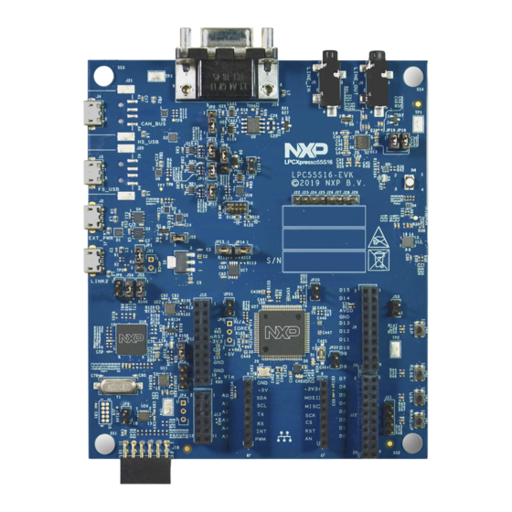
11: Analog comparator Input/O utput (open) P3: E xternal UART P21: VDDA power (closed) (1 RXD 2 TXD, 3 G N D) Fig. Default jumper locations Part Number: LPC55S16-EVK Agile Number: 926-78992 www nxp com Fig 2. Default jumper positions UM11158 All information provided in this document is subject to legal disclaimers. - Page 6 UM11158 NXP Semiconductors LPCXpresso55S16 Development Boards J8, J7 J9, J12 J10, J13 Fig 3. Board connectors and headers Table 1. Indicators, buttons, connectors and LEDs Circuit Description Default Reference reference Target power indicator LED Link2 boot LED Section 4.1 RGB User LED Section 7.5...
- Page 7 UM11158 NXP Semiconductors LPCXpresso55S16 Development Boards Table 1. Indicators, buttons, connectors and LEDs Circuit Description Default Reference reference Target processor selection for the on-board Debug Probe. Open Section 4. Jumper open (default) the LPC55Sxx Target SWD interface enabled. Normal operating mode where the Target SWD is connected to either the on-board Link2 Debug Probe or an external Debug Probe.
- Page 8 UM11158 NXP Semiconductors LPCXpresso55S16 Development Boards Table 1. Indicators, buttons, connectors and LEDs Circuit Description Default Reference reference LPC55Sxx USB0 (full speed) micro AB port connector LPC55Sxx USB Ports JP20 Power to MCU VDD, once removed, it can be used to measure VDD...
-
Page 9: Getting Started
UM11158 NXP Semiconductors LPCXpresso55S16 Development Boards Table 1. Indicators, buttons, connectors and LEDs Circuit Description Default Reference reference Wake/User button Section 7.6.2 This button, when pressed, pulls P1_18 to ground. A 330K ohm pull up to VDD is connected to P1_18. -
Page 10: Installation Steps For Use With Mcuxpresso Ide
UM11158 NXP Semiconductors LPCXpresso55S16 Development Boards NOTE: if the Debug Probe is set up to boot in DFU mode, the USB bridge functions (virtual COM port) and Debug Probe features will not be available if the board is not first initialized by the MCUXpresso IDE. -
Page 11: Starting A Debug Session Using An External Debug Probe
UM11158 NXP Semiconductors LPCXpresso55S16 Development Boards When the board is used for the first time, it is recommended to force the target into known state by performing an ISP boot before attempting to run your first example code. This can be achieved by pressing and holding down the ISP button while pressing and releasing the reset button. -
Page 12: On-Board (Link2) Debug Probe
UM11158 NXP Semiconductors LPCXpresso55S16 Development Boards 4. On-board (Link2) Debug probe This section describes the features provided by the on-board Link2 Debug Probe, including how to use this to debug an exernal target. The Link2 Debug Probe is implemented using an LPC432x MCU (circuit reference U16), which provides a high speed USB port interface to the host computer that runs the development tools. -
Page 13: Link2 Boot Led
UM11158 NXP Semiconductors LPCXpresso55S16 Development Boards 4.1 Link2 boot LED LED D8 is the Link2 MCU BOOT0_LED indicator. This LED reflects the state of Link2 MCU pin P1_1. When the boot process fails, D8 will toggle at a 1 Hz rate for 60 seconds. -
Page 14: Board Power
UM11158 NXP Semiconductors LPCXpresso55S16 Development Boards 5. Board Power The LPCXpresso55S16 board requires +5V input to power the on-board voltage low dropout linear regulators, of which there are 3, circuit reference U1, U3 and U4. . The Link2 Debug probe has a 2.5V regulator (U1) which draws power from USB connector J1 ("Debug Link") only. -
Page 15: Usart Header
UM11158 NXP Semiconductors LPCXpresso55S16 Development Boards used to connect power from a load switch to the VBUS signal of the port selected; JP2 should be placed in position 1-2 for USB0 or position 2-3 for USB1. If neither USB port is being used as a USB host this jumper is not required. -
Page 16: Can-Fd Connector
UM11158 NXP Semiconductors LPCXpresso55S16 Development Boards 7.2 CAN-FD Connector The LPC55S16 MCU includes a CAN-FD controller. On LPCXpresso55S16 board, P1.22 (IOCON Function 9) and P1.27 (IOCON Function 9) are configured as CAN_RXD and CAN_TXD respectively. A CAN-FD transceiver, U9, TJA1044, is populated on the board with level shifters between LPC55S16 target and CAN-FD transceiver to support both 1.8V and 3.3V. -
Page 17: User (Sw3) And Wakeup (Sw1) Buttons
UM11158 NXP Semiconductors LPCXpresso55S16 Development Boards The ISP button can also be used in user application code. Care should be taken if P0_5 is configured as an output driving high, since pressing this button will short it to ground. Note that jumper JS3 may also be used as a convenient way to always assert ISP when the LPC55Sxx is reset or powered up. -
Page 18: Board Power
UM11158 NXP Semiconductors LPCXpresso55S16 Development Boards Table 3. Arduino and LPCXpresso V3 expansion connections Expansion connector Port The odd number pins are compatible with Arduino Uno rev3 Digital 15:8, AREF, SDA & SCL connector. The even numbered pins are used for external access and expansion of LPC55Sxx signals not used by the Arduino Uno rev3 compatible interface. -
Page 19: Legal Information
Suitability for use — NXP Semiconductors products are not designed, authorized or warranted to be suitable for use in life support, life-critical or safety-critical systems or equipment, nor in applications where failure or malfunction of an NXP Semiconductors product can reasonably be expected to result in personal injury, death or severe property or environmental damage. -
Page 20: Table Of Contents
UM11158 NXP Semiconductors LPCXpresso55S16 Development Boards 12. Contents Introduction ......3 Board layout and Settings ....5 Getting started . - Page 21 UM11158 NXP Semiconductors LPCXpresso55S16 Development Boards UM11158 All information provided in this document is subject to legal disclaimers. © NXP B.V. 2020. All rights reserved. User manual Rev. 1.0 — 6 March 2020 21 of 21...
Need help?
Do you have a question about the LPC55S16-EVK and is the answer not in the manual?
Questions and answers