Fröling TI 350 Operating Instructions Manual
Wood chip boiler
Hide thumbs
Also See for TI 350:
- Installation instructions manual (76 pages) ,
- Service handbook (116 pages)
Table of Contents
Advertisement
Quick Links
Operating Instructions
Wood chip boiler TI 350
Translation of the original German operating instructions for the operator
Read and follow the instructions and safety information!
Technical changes, typographical errors and omissions reserved!
B1380220_en | Edition 16/03/2020
Froling GesmbH | A-4710 Grieskirchen, Industriestraße 12 | www.froeling.com
Advertisement
Table of Contents

Related Manuals for Fröling TI 350


Summary of Contents for Fröling TI 350
- Page 1 Operating Instructions Wood chip boiler TI 350 Translation of the original German operating instructions for the operator Read and follow the instructions and safety information! Technical changes, typographical errors and omissions reserved! B1380220_en | Edition 16/03/2020 Froling GesmbH | A-4710 Grieskirchen, Industriestraße 12 | www.froeling.com...
-
Page 2: Table Of Contents
Table of contents Table of contents General Product overview Safety Hazard levels of warnings Pictograms used General safety information Permitted uses 2.4.1 The Clean Air Act 1993 and Smoke Control Areas 2.4.2 Permitted fuels Wood chips Wood pellets Wood shavings Miscanthus Changing the fuel 2.4.3... - Page 3 Periodic inspection and cleaning (approx. 3,000 hrs) Cleaning the fireclay elements Setting and checking the seal on the door Adjusting the door Cleaning the induced draught fan Checking the heat exchanger ash removal drive Operating Instructions TI 350 | B1380220_en...
- Page 4 Table of contents Checking the underpressure controller Lubricating the bearings Checking the flue gas pipe Check the igniter tube Maintenance work by technicians 5.4.1 Cleaning the Lambda probe Maintenance instructions for hydraulic system Emissions measurement by chimney sweep or regulatory body 5.6.1 Switch on the system 5.6.2...
-
Page 5: General
Our sale and delivery conditions will be applicable. These conditions have been made available to customers, and customers have been made aware of them at the time of order completion. You can also find the guarantee conditions on the enclosed guarantee certificate. Operating Instructions TI 350 | B1380220_en... -
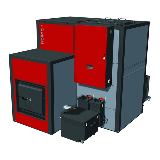
Page 6: Product Overview
General Product overview 1.1 Product overview Wood chip boiler - Froling TI Control cabinet with integrated Lambdatronic H 3200 controller Main switch: switches the power supply on and off for the entire system Control panel of the Lambdatronic H 3200 - Touch controller Status LED (operating status) - GREEN constant: BOILER SWITCHED ON - GREEN flashing (interval: 5 sec OFF, 1 sec ON): BOILER SWITCHED OFF... - Page 7 Fuel transport unit with rotary valve as burn back protection (BBF) and stoker screw for fuel transport Moving grate with automatic drive Efficiency Optimisation System (EOS) with turbulators Combustion chamber door Combustion chamber, complete Heat exchanger, complete Burn through elbow with safety battery Operating Instructions TI 350 | B1380220_en...
- Page 8 General Product overview Automatic drive for Efficiency Optimisation System (WOS) Boiler flow connection Boiler return connection Induced draught fan Flue gas recirculation (FGR) Secondary air control with servo-motor drive Combustion chamber temperature sensor (behind cover) Under-pressure controller High-limit thermostat STL (heat exchanger) High-limit thermostat STL (behind cover) Thermal discharge valve connection (heat exchanger) Thermal discharge valve connection (burn through elbow)
- Page 9 General Product overview Primary air control with servo-motor drive (behind cover) Undergrate thermostat Operating Instructions TI 350 | B1380220_en...
-
Page 10: Safety
Safety Hazard levels of warnings 2 Safety 2.1 Hazard levels of warnings This documentation uses warnings with the following hazard levels to indicate direct hazards and important safety instructions: DANGER The dangerous situation is imminent and if measures are not observed it will lead to serious injury or death. -
Page 11: Pictograms Used
Warning - hazardous or irritant Warning - automatic boiler materials startup Hand injury warning Warning of injury to fingers or hands, automatic fan Cutting injury warning Warning of injury to fingers or hands, automatic screw Operating Instructions TI 350 | B1380220_en... -
Page 12: General Safety Information
Safety General safety information 2.3 General safety information DANGER If the device is used incorrectly: Incorrect use of the system can cause severe injury and damage. When operating the system: ❒ Observe the instructions and information in the manuals. ❒ Observe the details on procedures for operation, maintenance and cleaning, as well as troubleshooting in the individual manuals. -
Page 13: Permitted Uses
Clean Air Act requirements. The Froling TI 350 Wood Chip and Wood Pellet 350 kW boilerhas been recommended as suitable for use in smoke control areas when burning Wood Chips and Wood Pellets. -
Page 14: Permitted Fuels
Safety Permitted uses 2.4.2 Permitted fuels Wood chips Criterion Designation as per Description acc. to ÖNORM M 7133 ÖNORM M 7133 EN ISO 17225 Water content air-dried suitable for storage Size P16S Fine wood chip P31S Medium-sized wood chip Note on standards Fuel acc. -
Page 15: Miscanthus
Using non-standard fuels can also lead to serious problems with combustion. For this reason, when operating the boiler: ❒ Only use permitted fuels Operating Instructions TI 350 | B1380220_en... -
Page 16: Qualification Of Operating Staff
Safety Permitted uses 2.4.4 Qualification of operating staff CAUTION If unauthorised persons enter the Boiler room: Risk of personal injury and damage to property ❒ The operator is responsible for keeping unauthorised persons, in particular children, away from the system. Only trained operators are permitted to operate the unit. -
Page 17: Safety Devices
Once the temperature falls below approx. 75°C, the STL can be reset mechanically. DOOR CONTACT SWITCH When the door is opened, the induced draught is kept at a constant speed. Operating Instructions TI 350 | B1380220_en... -
Page 18: External Safety Devices
Safety Safety devices (protection against overheating) THERMAL DISCHARGE VALVE The thermal discharge valve opens at approx. 100°C and feeds cold water to the safety heat exchanger to lower the boiler temperature (not shown, supplied by the customer) SAFETY VALVE When the boiler pressure reaches a maximum of 6 bar, the safety valve opens and the heating water is released in the form of steam. -
Page 19: Residual Risks
Non-standard fuels can cause serious faults in combustion (e.g. spontaneous combustion of carbonisation gases / flash fires) which can lead to serious accidents! Take the following precautions: ❒ Only use fuels specified in the "Permitted fuels" section of these operating instructions. Operating Instructions TI 350 | B1380220_en... - Page 20 Safety Residual risks WARNING Inspection and cleaning work on a system which is operational: Risk of serious injuries from automatic startup of the system and severe burns from hot parts and the flue gas pipe! When working on the system: ❒...
-
Page 21: Emergency Procedure
In case of fire in the system: Risk of death by fire and poisonous gases Emergency procedure in case of fire: ❒ Leave the boiler room ❒ Close the doors ❒ Inform the fire department Operating Instructions TI 350 | B1380220_en... -
Page 22: Notes For Operating A Heating System
Notes for operating a heating system Installation and approval of the heating system 3 Notes for operating a heating system Carrying out modifications to the system and changing or disabling safety equipment is prohibited. Always comply with all fire, building and electrical regulations when installing or operating the system, in addition to following the operating instructions and mandatory regulations that apply in the country in which the tank is operated. -
Page 23: Requirements For Central Heating Water
❒ Avoid leaks and use a closed heating system to maintain water quality during operation ❒ When filling with make-up water, always bleed the filling hose before connecting, in order to prevent air from entering the system Operating Instructions TI 350 | B1380220_en... - Page 24 Notes for operating a heating system Requirements for central heating water Advantages of prepared water: ▪ Complies with the applicable standards ▪ Less of a drop in output due to reduced limescale build-up ▪ Less corrosion due to fewer aggressive substances ▪...
-
Page 25: Notes For Using Pressure Maintenance Systems
Take the following precautions: ❒ Regulations stipulate the use of a return temperature control. ➥ The minimum return temperature is 60 °C. We recommend fitting some sort of control device (e.g. thermometer). Operating Instructions TI 350 | B1380220_en... -
Page 26: Use With Storage Tank
Notes for operating a heating system Use with storage tank 3.6 Use with storage tank NOTICE In principle it is not necessary to use a storage tank for the system to run smoothly. However, we recommend that you use the system with a storage tank, as this ensures a continuous supply of fuel in the ideal output range of the boiler. -
Page 27: Operating The System Assembly And Initial Startup
▪ During initial start-up, operating staff are shown how to use the boiler. It is imperative for proper handover of the product that those involved are present as this is a one-off opportunity. Operating Instructions TI 350 | B1380220_en... -
Page 28: Filling/Refilling The Store With Fuel
Operating the system Filling/refilling the store with fuel NOTICE If condensation escapes during the initial heat-up phase, this does not indicate a fault. ❒ Tip: If this occurs, clean up using a cleaning rag. 4.2 Filling/refilling the store with fuel When filling the store you should always ensure that you are using the right fuel: 4.2.1 Loading of fuel for a partially emptied store with rotary agitator If there is still sufficient fuel in the store (the head of the rotary agitator is completely... -
Page 29: Blowing In Pellets For A Store With Pellet Screw
❒ Switch off the boiler by tapping “Boiler off” at the mode icon and allow to cool for at least two hours ❒ Close all openings to the store to seal out dust ❒ Blow the fuel into the store Operating Instructions TI 350 | B1380220_en... -
Page 30: Blowing In Fuel For An Empty Store With Rotary Agitator
Operating the system Filling/refilling the store with fuel 4.2.5 Blowing in fuel for an empty store with rotary agitator NOTICE! If the head of the rotary agitator is already free of material and the arms / spring blades are extended, the store must not be filled until the following actions have been taken: ❒... -
Page 31: Drainage Of Fuel Store
▪ Reduce the dumping height onto the rotary agitator ▪ Avoid compressing the wood chips, e.g. by carefully adding to the fuel store ▪ Design the walls in the bunker so they are as smooth as possible Operating Instructions TI 350 | B1380220_en... -
Page 32: Switching On The Power Supply
Operating the system Switching on the power supply 4.3 Switching on the power supply ❒ Turn on the main switch ➥ There is voltage at all of the boiler's components ➥ When the control has completed the system start, the boiler is ready for operation 4.4 Operate the boiler using the touch display 4.4.1 Overview of the touch display... -
Page 33: Status Display
Discards any values entered without saving; and closes messages Back to basic display Accesses all system information Opens quick menu. Selection of functions depending on user level, configuration and current status. Tap to change parameters (dropdown menu or numeric keypad) Operating Instructions TI 350 | B1380220_en... -
Page 34: Display Icons For Froeling-Connect/Remote Control
Operating the system Operate the boiler using the touch display Opens system menu. Menu display depends on user level and configuration Back to higher menu level. Display icons for froeling-connect/remote control The icons for connection status and remote control are displayed at the top left of the touch display. -
Page 35: Navigation Within The System Menu
Tap the respective tab to carry out settings in the menus. Icon Status Temperatures Times Service General settings Solar heat meter Operating Instructions TI 350 | B1380220_en... -
Page 36: Changing Parameters
Operating the system Operate the boiler using the touch display Changing parameters If there is a “pencil” symbol next to a parameter text, the parameter can be edited. Depending on the type of parameter, it can be edited using the numeric keypad or by selecting from a list and then tapping on the “Confirm”... -
Page 37: Quick Menu
List of all pending boiler faults and how to eliminate them. Setting wizard Switching on for the first time: Setting the language, production number, date and time Connect: Setting parameters required for the boiler to use the “froeling-connect.com” (IP address, display password, …) Operating Instructions TI 350 | B1380220_en... -
Page 38: Select Information Displays
Operating the system Operate the boiler using the touch display 4.4.2 Select information displays Tapping on the freely selectable information displays in the basic display opens the respective menu. The following options are available depending on the system configuration: Menu Selection Icon Description... - Page 39 System CPU/RAM capacity Display of the CPU and RAM capacity in percent 1. This selection merges two tiles together, reducing the maximum number of information displays! Operating Instructions TI 350 | B1380220_en...
- Page 40 Operating the system Operate the boiler using the touch display When using more than two store sensors, it is possible to have an information display with storage tank temperatures in accordance with the number of sensors. An information display that spans two areas is used. Froling GesmbH | A-4710 Grieskirchen, Industriestraße 12 | www.froeling.com...
-
Page 41: Change Boiler Mode
Supply heating circuits and domestic hot water tanks with heat according to the selected heating times. NOTICE! Consult the enclosed operating instructions for the boiler controller for a detailed description of the boiler modes. Operating Instructions TI 350 | B1380220_en... -
Page 42: Change Date And Time
Operating the system Operate the boiler using the touch display 4.4.4 Change date and time Tap on the displayed date and time to change the date and time in the basic display. Use the up and down arrows to adjust the settings and tap on the “Confirm” icon to save. -
Page 43: One-Time Extra Loading Of An Individual Dhw Tank
In the case of several DHW tanks, the “extra loading” function in the quick menu is used to start a one-time extra loading of all existing DHW tanks. ⇨ See "Quick menu" [page 37] Operating Instructions TI 350 | B1380220_en... -
Page 44: Set The Heating Curve Of A Heating Circuit
Operating the system Operate the boiler using the touch display 4.4.8 Set the heating curve of a heating circuit A flow temperature is calculated using the heating curve of the heating circuit Example of depending on the outside air temperature and the two adjustable parameters “flow floor heating temperature at -10°C outside air temperature”... -
Page 45: Change Room Temperature (Heating Circuit Without Room Temperature Sensor)
4.4.10 Change room temperature (heating circuit mit room temperature sensor) ❒ Tap information display of the desired heating circuit ❒ Tap “+” or “-” to adjust the desired room temperature Operating Instructions TI 350 | B1380220_en... -
Page 46: Switch Heating Circuit Mode
Operating the system Operate the boiler using the touch display NOTICE! If this selection is not configured in the information display in the basic display, open the components in the system menu. Otherwise, the room temperature can be adjusted directly on the remote control/room console. -
Page 47: Lock Display/Switch User Level
The names of the DHW tank, storage tank and heating circuits can be freely selected. A maximum of 20 characters are available for the name. ❒ Navigate to the “System” menu and open the “Renaming” sub-menu ❒ Tap the desired component and use the keyboard to rename it Operating Instructions TI 350 | B1380220_en... -
Page 48: Configure The Holiday Program
Operating the system Operate the boiler using the touch display 4.4.14 Configure the holiday program Setting a start and end date in the holiday program determines a time period in which an active heating circuit is regulated for the set setback temperature and in which an activated boiler is not loaded. -
Page 49: Switch The Boiler On/Off On The Room Console
[page 34]), the boiler can be switched on and off on the room console. Boiler remote control deactivated Boiler remote control activated ❒ Switch the boiler ON/OFF by tapping on the current operating status Operating Instructions TI 350 | B1380220_en... -
Page 50: Switching Off The Power Supply
Operating the system Switching off the power supply 4.6 Switching off the power supply WARNING When turning off the main switch in automatic mode: Serious combustion faults leading to serious accidents are possible. Before turning off the main switch: ❒ Switch boiler off by tapping “Boiler OFF” ➥... -
Page 51: Checking The Fill Level Of The Ash Container And Emptying If Required
❒ Push the side lever up to release the ash container ❒ Pull out the ash container ❒ Push the front coupling cap onto the ash container ❒ Take the ash container to the emptying point and empty it Operating Instructions TI 350 | B1380220_en... -
Page 52: Emptying The Heat Exchanger Ash Container
Operating the system Checking the fill level of the ash container and emptying if required Replace the ash container: ❒ Press the clip on the front coupling cap to release it ❒ Remove the coupling cap ❒ Replace the ash container ❒... - Page 53 ❒ Press the clip on the front coupling cap to release it ❒ Remove the coupling cap and insert the ash container ❒ Push the lever down to lock the ash container ❒ Push the key plate into the safety switch Operating Instructions TI 350 | B1380220_en...
-
Page 54: Servicing The System
Servicing the system General information on servicing 5 Servicing the system 5.1 General information on servicing DANGER When working on electrical components: Risk of electrocution! When work is carried out on electrical components: ❒ Always have work carried out by a qualified electrician ❒... - Page 55 M7510 of the Technical Directive for Fire Prevention (TRVB) NOTICE As well as the cleaning and maintenance tasks explained in these instructions, also refer to the specifications according to TRVB H 118 given in the enclosed inspection book. Operating Instructions TI 350 | B1380220_en...
-
Page 56: Required Tools
Servicing the system Required tools 5.2 Required tools The following tools are required for carrying out cleaning and maintenance work: Included in delivery: Flat scraper Chipper Spanner for door mountings Cleaning brush Ø 54 mm Cleaning brush Ø 83 mm Not included: Spanner or box wrench set Screwdriver set (Philips, flat head, Torx T20, T25, T30) -
Page 57: Maintenance Work By The Operator
➥ There should be no significant leakage of lubricant NOTICE! The presence of a few drops of lubricant may be normal. If there is significant loss of lubricant, inform your installer or Froling customer services Operating Instructions TI 350 | B1380220_en... -
Page 58: Checking The Quick Vent Valve
Servicing the system Maintenance work by the operator Checking the quick vent valve ❒ Regularly check all the quick vent valves on the entire heating system for leaks ➥ If any liquid is leaking, replace the quick vent valves NOTICE! The vent cap (A) must be loose (screw on approx. two revolutions) to ensure correct functioning. -
Page 59: Periodic Inspection And Cleaning
⇨ See "Setting and checking the seal on the door" ⇨ See "Check the igniter tube" [page 71] [page 67] ⇨ See "Cleaning the induced draught fan" [page 69] ⇨ See "Checking the underpressure controller" [page Operating Instructions TI 350 | B1380220_en... -
Page 60: Periodic Inspection And Cleaning (Approx. 1,000 Hrs)
Servicing the system Maintenance work by the operator 5.3.3 Periodic inspection and cleaning (approx. 1,000 hrs) For fuels with a low ash content, cleaning and inspection after approx. 1,000 service hours is usually sufficient (under normal use conditions, approximately every quarter). For less efficient fuels and fuels with a high ash content (indicated by short emptying intervals for the ash container), the work should be carried out correspondingly more frequently. -
Page 61: Cleaning The Ash From The Heat Exchanger
❒ Vacuum any deposits where necessary ❒ If necessary, pull the entire unit out of the heat exchanger pipes and then clean both the pipes and the turbulators with a brush or an ash vacuum Operating Instructions TI 350 | B1380220_en... -
Page 62: Clean The Flue Gas Temperature Sensor
Servicing the system Maintenance work by the operator ❒ Remove the cover from the combustion pipe. ❒ Clean the cover, the pipe and the burn through elbow between the combustion chamber and the heat exchanger ❒ Refit the cover Clean the flue gas temperature sensor ❒... -
Page 63: Cleaning The Flue Gas Recirculation (Agr)
❒ Undo the screws and remove the inspection cover incl. torque support ❒ Clean the interior with an ash vacuum ❒ Remove the inspection cover from the settling chamber ❒ Clean the interior with an ash vacuum Operating Instructions TI 350 | B1380220_en... -
Page 64: Cleaning The Area Under The Moving Grate
Servicing the system Maintenance work by the operator Cleaning the area under the moving grate ❒ Undo the six captive screws (A) and remove the cover plate ❒ Remove the thermal insulation ➥ If necessary, cut out the thermal insulation ❒... -
Page 65: Lubricate The Stoker Bearings
Maintenance work by the operator Lubricate the stoker bearings ❒ Lubricate stoker bearings with three grease gun strokes per grease nipple ➥ IMPORTANT! Carry out the lubrication process slowly to avoid damage to the bearing seals Operating Instructions TI 350 | B1380220_en... -
Page 66: Periodic Inspection And Cleaning (Approx. 3,000 Hrs)
Servicing the system Maintenance work by the operator 5.3.4 Periodic inspection and cleaning (approx. 3,000 hrs) For fuels with a low ash content, cleaning and inspection after approx. 3,000 service hours is usually sufficient (under normal use conditions, approximately once a year). For less efficient fuels and fuels with a high ash content (indicated by short emptying intervals for the ash container), the work should be carried out more frequently accordingly. -
Page 67: Setting And Checking The Seal On The Door
➥ The door can be closed with a normal amount of effort: does not require adjustment. ➥ The door cannot be closed or can only be closed with great effort: loosen the locking hook. ⇨ See "Adjusting the door" [page 68] Operating Instructions TI 350 | B1380220_en... -
Page 68: Adjusting The Door
Servicing the system Maintenance work by the operator Checking the seal ❒ Open the door ❒ Insert a sheet of paper at both the top and the bottom between the door and the boiler. ❒ Close the door. ❒ Try to pull out the sheet of paper. ➥... -
Page 69: Cleaning The Induced Draught Fan
❒ Take out the induced draught fan and clean the blower wheel with a brush ❒ Clean the interior of the induced draught fan housing with an ash vacuum NOTICE! Refer to the marked position of the flange when refitting. Operating Instructions TI 350 | B1380220_en... -
Page 70: Checking The Heat Exchanger Ash Removal Drive
Servicing the system Maintenance work by the operator Checking the heat exchanger ash removal drive ❒ Remove the cover ❒ Grease the chain drive and check for wear ❒ Check the chain tension and adjust where necessary Checking the underpressure controller ❒... -
Page 71: Check The Igniter Tube
❒ Remove the protective plates on the ignition next to the fuel feed-in ❒ Loosen the double wire hose clip and pull the ignition out of the igniter tube ❒ Check the igniter tube (A) for dirt and deposits and clean if necessary Operating Instructions TI 350 | B1380220_en... -
Page 72: Maintenance Work By Technicians
Servicing the system Maintenance work by technicians 5.4 Maintenance work by technicians CAUTION If maintenance work is carried out by untrained personnel: Risk of personal injury and damage to property! The following applies for maintenance: ❒ Observe the instructions and information in the manuals ❒... -
Page 73: Cleaning The Lambda Probe
➥ CAUTION: Do not use sharp objects or compressed air to clean the Lambda probe ❒ Screw the Lambda probe back on again by hand ➥ IMPORTANT: The seal surface of the bushing (C) must lie flat on the sleeve after assembly Operating Instructions TI 350 | B1380220_en... -
Page 74: Maintenance Instructions For Hydraulic System
Servicing the system Maintenance instructions for hydraulic system 5.5 Maintenance instructions for hydraulic system WARNING Do not use unskilled personnel for hydraulic system maintenance Risk of injury and damage to property! Take the following precautions: ❒ Only allow trained professionals to carry out servicing and maintenance work on the hydraulic system. -
Page 75: Emissions Measurement By Chimney Sweep Or Regulatory Body
➥ Automatic mode is active. The heating system is controlled via the controller according to the selected mode in automatic mode 5.6.2 Start emissions measurement ❒ Activate the “Chimney-sweep mode” icon ❒ Select the desired time from the menu: Operating Instructions TI 350 | B1380220_en... -
Page 76: Replacement Parts
Servicing the system Replacement parts immediately ❒ Specify the type of measurement (nominal load / partial load) ➥ The flue gas temperature and residual oxygen content should have stabilised approximately 20 minutes after activation ➥ The display will indicate that the boiler is ready for measurement as soon as all the conditions for the measurement are fulfilled 5.7 Replacement parts With Froling original replacement parts in your boiler, you are using parts that match... -
Page 77: Troubleshooting
95 - 100°C. The pumps continue to run. Once the temperature falls below approx. 75°C, the STL can be unlocked mechanically: ❒ Unscrew the cap on the STL (high-limit thermostat) ❒ Unlock the STL by pressing with a screwdriver Operating Instructions TI 350 | B1380220_en... -
Page 78: Faults With Fault Message
Troubleshooting Faults with fault message 6.3 Faults with fault message If a fault has occurred and has not yet been cleared: ❒ Status LED indicates the nature of the fault - Orange flashing: Warning - Red flashing: Error or alarm ❒... - Page 79 Faults with fault message ❒ Press the “Error resolution” tab to view possible causes and troubleshooting procedures ❒ Once the fault has been resolved, tap the Cancel icon to return to the basic display. Operating Instructions TI 350 | B1380220_en...
-
Page 80: Appendix Addresses
Appendix Addresses 7 Appendix 7.1 Addresses 7.1.1 Address of manufacturer FRÖLING Heizkessel- und Behälterbau GesmbH Industriestraße 12 A-4710 Grieskirchen AUSTRIA TEL 0043 (0)7248 606 0 FAX 0043 (0)7248 606 600 EMAIL info@froeling.com INTERNET www.froeling.com Customer service Austria 0043 (0)7248 606 7000 Germany 0049 (0)89 927 926 400 Worldwide...
Need help?
Do you have a question about the TI 350 and is the answer not in the manual?
Questions and answers