Sign In
Upload
Manuals
Brands
Fröling Manuals
Boiler
TI 350
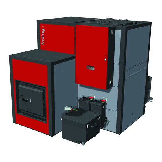
Fröling TI 350 Wood chip boiler Manuals
Manuals and User Guides for Fröling TI 350 Wood chip boiler. We have
3
Fröling TI 350 Wood chip boiler manuals available for free PDF download: Service Handbook, Operating Instructions Manual, Installation Instructions Manual
Fröling TI 350 Service Handbook (116 pages)
Brand:
Fröling
| Category:
Boiler
| Size: 9 MB
Table of Contents
Table of Contents
2
General
5
About These Instructions
5
Safety Information
5
Power Connection and Wiring
6
Core Module and Connection Options
6
Board View - Core Module
6
Mains Connection
8
Connecting the Outside Temperature Sensor
8
FRA Room Temperature Sensor
9
Boiler Enable Contact
9
Connecting a Circulating Pump to the Core Module
10
Connecting a Circulating Pump with Valve to the Core Module
12
Heating Circuit Pump 0 / Burner Relay
14
Operating Signal
14
Expansion Modules
15
Heating Circuit Module
15
Hydraulic Module
16
Wood Chip Module
22
Plug Power Pack FRSNT17
23
Plug Power Pack Meanwell LRS-100-24
23
Analogue Module
24
Digital Module
26
BUS Connection
28
Connecting the Bus Cable
29
Setting End Jumpers
29
Setting the Module Address
30
Potential Equalisation / Potential Separation
31
Connection Information According to Pump Types
32
Frequency Converter
33
Operating Elements
33
Changing Parameters
34
Initial Start-Up with Settings Wizards
36
Before Switching on for the First Time
36
Controller Check
36
Check on the Connected Units
36
System Check
36
General Information about the Settings Wizard
37
Switching on for the First Time
38
Starting the Setting Wizard
39
Parameters Overview
41
Heating
41
Heating - Status
41
Heating - Temperatures
41
Heating - Times
42
Heating - Service
43
Heating - Heating up Program
44
Heating - General Settings
46
Water
46
Water - Status
46
Water - Temperatures
47
Water - Times
47
Water - Service
47
Solar
48
Solar - Status
48
Solar - Temperatures
50
Solar - Times
50
Solar - Service
51
Solar - Heat Meter
52
Buffer Tank
53
Buffer Tank - Status
53
Buffer Tank - Temperatures
54
Buffer Tank - Times
55
Buffer Tank - Service
55
Boiler
56
Boiler - Status
56
Boiler - Temperatures
56
Boiler - Times
57
Boiler - Service
58
Boiler - General Settings
58
Boiler 2
60
Boiler 2 - Status
60
Boiler 2 - Temperatures
61
Boiler 2 - Service
62
Fuel
62
Fuel - Parameter
62
Feed System
63
Feed System - Screw 1 on LB
63
Feed System - Cyclone 1
63
Network Pump
65
Network Pump - Status
65
Network Pump - Temperatures
65
Network Pump - Service
66
Cascade
67
Cascade - Status
67
Cascade - Temperatures
68
Cascade - Service
69
Difference Regulator
71
Difference Regulator - Status
71
Difference Regulator - Temperatures
71
Difference Regulator - Times
71
Difference Regulator - Service
72
Circulation Pump
72
Circulation Pump - Status
72
Circulation Pump - Temperatures
73
Circulation Pump - Times
73
Circulation Pump - Service
73
Manual
74
Manual - Manual Operation
74
Manual - Digital Outputs
75
Manual - Analogue Outputs
75
Manual - Digital Inputs
76
System
76
System - Setting
76
System - Current Values
87
System - Sensors and Pumps
87
System - System Selection
87
Diagnostics
88
Diagnosis - Current Fault List
88
Diagnosis - Clear Pending Error
88
Diagnostics - Error History
88
Diagnostics - Clear Error History
88
Touchscreen
89
Touchscreen - Display Settings
89
Touchscreen - Display Operating Rights
90
Touchscreen - Display Allocation
92
Faq
93
Activation Options of Pump Outlets
93
Pump Stall Protection
94
Boiler Operating Statuses
95
Determination of the Quantity of Heat
96
Assembly Information
96
Functioning and Configuration
96
Boiler Modes
98
Automatic" Mode Without Storage Tank
98
Automatic" Mode with Storage Tank
99
Continuous Load" Mode Without Storage Tank
100
Continuous Load" Mode with Storage Tank
100
Domestic Hot Water" Mode Without Storage Tank
101
Domestic Hot Water" Mode with Storage Tank
102
Setting Times
103
Calibrating the Touchscreen
105
Software Update Lambdatronic 3200
107
Carrying out a Software Update on the Boiler Controller
108
Carrying out a Software Update on the Touch Control
110
Finishing a Software Update
111
USB Data Recording
112
Advertisement
Fröling TI 350 Operating Instructions Manual (80 pages)
Wood chip boiler
Brand:
Fröling
| Category:
Boiler
| Size: 20 MB
Table of Contents
Table of Contents
2
1 General
5
Product Overview
6
2 Safety
10
Hazard Levels of Warnings
10
Pictograms Used
11
General Safety Information
12
Permitted Uses
13
The Clean Air Act 1993 and Smoke Control Areas
13
Permitted Fuels
14
Wood Chips
14
Wood Pellets
14
Wood Shavings
14
Miscanthus
15
Changing the Fuel
15
Non-Permitted Fuels
15
Qualification of Operating Staff
16
Protective Equipment for Operating Staff
16
Safety Devices
17
External Safety Devices
18
Hydraulic Chamber Safety Switch
18
Guardrail
18
Residual Risks
19
Emergency Procedure
21
Overheating of the System
21
Smell of Flue Gas
21
Fire in the System
21
3 Notes for Operating a Heating System
22
Installation and Approval of the Heating System
22
General Information for Installation Room (Boiler Room)
22
Requirements for Central Heating Water
23
Notes for Using Pressure Maintenance Systems
25
Return Lift
25
Use with Storage Tank
26
Chimney Connection/Chimney System
26
Operating the System Assembly and Initial Startup
27
4 Operating the System
28
Filling/Refilling the Store with Fuel
28
Loading of Fuel for a Partially Emptied Store with Rotary Agitator
28
Loading Wood Chips in an Empty Store (Not under Pressure)
28
Blowing in Pellets for a Store with Pellet Screw
29
Blowing in Fuel for a Partially Emptied Store with Rotary Agitator
29
Blowing in Fuel for an Empty Store with Rotary Agitator
30
Drainage of Fuel Store
31
Switching on the Power Supply
32
Operate the Boiler Using the Touch Display
32
Overview of the Touch Display
32
Status Display
33
Control Icons
33
Display Icons for Froeling-Connect/Remote Control
34
Navigation Within the System Menu
35
Changing Parameters
36
Change Time Window
36
Quick Menu
37
Select Information Displays
38
Change Boiler Mode
41
Change Date and Time
42
Change Desired DHW Tank Temperature
42
One-Time Extra Loading of an Individual DHW Tank
43
One-Time Extra Loading of All Existing DHW Tanks
43
Set the Heating Curve of a Heating Circuit
44
Change Room Temperature (Heating Circuit Without Room Temperature Sensor)
45
Change Room Temperature (Heating Circuit mit Room Temperature Sensor)
45
Switch Heating Circuit Mode
46
Lock Display/Switch User Level
47
Change the Name of the Components
47
Configure the Holiday Program
48
Switch the Boiler ON/OFF on the Room Console
49
Switching off the Power Supply
50
Checking the Fill Level of the Ash Container and Emptying if Required
51
Emptying the Combustion Chamber Ash Container
51
Emptying the Heat Exchanger Ash Container
52
5 Servicing the System
54
General Information on Servicing
54
Required Tools
56
Maintenance Work by the Operator
57
Inspection
57
Checking the System Pressure
57
Checking the Thermal Discharge Safety Device
57
Checking the Safety Valve
57
Checking the Geared Motors
57
Checking the Quick Vent Valve
58
Checking the Draught Controller Flap
58
General Weekly Inspection
58
Periodic Inspection and Cleaning
59
Periodic Inspection and Cleaning (Approx. 1,000 Hrs)
60
Cleaning the Ash from the Heat Exchanger
61
Cleaning the Heat Exchanger
61
Clean the Flue Gas Temperature Sensor
62
Cleaning the Flue Gas Recirculation (AGR)
63
Cleaning the Area under the Moving Grate
64
Lubricate the Stoker Bearings
65
Periodic Inspection and Cleaning (Approx. 3,000 Hrs)
66
Cleaning the Fireclay Elements
66
Setting and Checking the Seal on the Door
67
Adjusting the Door
68
Cleaning the Induced Draught Fan
69
Checking the Heat Exchanger Ash Removal Drive
70
Checking the Underpressure Controller
70
Lubricating the Bearings
70
Checking the Flue Gas Pipe
70
Check the Igniter Tube
71
Maintenance Work by Technicians
72
Cleaning the Lambda Probe
73
Maintenance Instructions for Hydraulic System
74
Emissions Measurement by Chimney Sweep or Regulatory Body
75
Switch on the System
75
Start Emissions Measurement
75
Replacement Parts
76
Disposal Information
76
Disposal of the Ash
76
Disposal of System Components
76
6 Troubleshooting
77
General Faults in the Power Supply
77
Behaviour of System after a Power Failure
77
Excessive Temperature
77
Faults with Fault Message
78
Procedure for Fault Messages
78
Appendix Addresses
80
7 Appendix Address of Manufacturer
80
Address of the Installer
80
Customer Service
80
Fröling TI 350 Installation Instructions Manual (76 pages)
Brand:
Fröling
| Category:
Boiler
| Size: 20 MB
Table of Contents
Table of Contents
2
1 General
5
2 Safety
6
Hazard Levels of Warnings
6
Qualification of Assembly Staff
7
Personal Protective Equipment for Assembly Staff
7
3 Design Information
8
Notes on Standards
8
General Standards for Heating Systems
8
Standards for Structural and Safety Devices
8
Standards for Heating Water
8
Regulations and Standards for Permitted Fuels
9
Installation and Approval of the Heating System
9
General Information for Installation Room (Boiler Room)
9
Requirements for Central Heating Water
10
Notes for Using Pressure Maintenance Systems
12
Return Lift
12
Use with Storage Tank
13
Chimney Connection/Chimney System
13
Draught Limiter
13
4 Technology
14
Dimensions
14
Components and Connections
15
Technical Data
16
Boiler Data for Planning the Flue Gas System
18
5 Assembly
19
Transport
19
Temporary Storage
19
Positioning
19
Setting up in the Boiler Room
20
Moving the Boiler in the Boiler Room
20
Operating and Maintenance Areas of the Equipment
21
Installing the Boiler
22
General Information
22
Installing the Grate Drive
23
Installing the Stoker Unit
24
Bolting Together the Combustion Chamber and Heat Exchanger
24
Repositioning the WOS Lever (if Required)
26
Fitting the WOS Drive
27
Installing the Air Controllers
28
Installing the Ash Removal Chamber
28
Installing the Heat Exchanger Ash Removal Unit
30
Installing the Air Ducts
32
Installing the Adapter Flange und Pump Assembly (Optional)
32
Installing the Igniter Tube and Undergrate Temperature Sensor
33
Installing the Spacer Plate on the Combustion Chamber
33
Positioning Two-Layer Thermal Insulation on the Combustion Chamber
34
Positioning Thermal Insulation on the Heat Exchanger
35
Installing the Frames
36
Preparing the Cooling Piping (Optional)
41
Installing the Cooling Piping (Optional)
41
Installing the Piping of the Safety Battery
42
Fit Sensor and Wire Components
43
Installing the Cladding
45
Fitting the Control Cabinet
48
Installing the Combustion Chamber Door Components
49
Installing the Ash Container Limit Switch
50
Installing the Combustion Chamber Temperature Sensor and Ignition
51
Installing the Underpressure Controller
52
Installing Remaining Covers
53
Installing the Broadband Probe and Flue Gas Temperature Sensor
54
Installing the Induced Draught Fan
54
Installing the Flue Gas Recirculation (FGR)
55
Positioning the Ash Container
59
Flue Gas Piping
60
Power Connection and Wiring
60
Potential Equalisation
61
Installing the Cable Duct Covers
61
Connecting the Hydraulic Safety Devices
62
Cooling Connection
64
Final Installation Steps
65
Setting and Checking the Seal on the Door
65
Adjusting the Door
66
6 Commissioning
67
Before Commissioning / Configuring the Boiler
67
Initial Startup
68
Permitted Fuels
68
Wood Chips
68
Wood Pellets
68
Wood Shavings
68
Miscanthus
69
Changing the Fuel
69
Non-Permitted Fuels
69
Heating up for the First Time
70
Screed Drying
71
7 Decommissioning
73
Out of Service for Long Periods
73
Disassembly
73
Disposal
73
8 Notes
74
9 Appendix
76
Advertisement
Advertisement
Related Products
Fröling TI
Fröling T4e 20-35
Fröling T4e 20
Fröling T4e 35
Fröling T4e 50
Fröling T4e 140
Fröling T4e 180
Fröling T4e 200
Fröling T4e 250
Fröling TM 320-550
Fröling Categories
Boiler
Industrial Equipment
Pellet stove
Boiler Supplies
Heating System
More Fröling Manuals
Login
Sign In
OR
Sign in with Facebook
Sign in with Google
Upload manual
Upload from disk
Upload from URL