Table of Contents
Advertisement
Quick Links
Advertisement
Table of Contents

Subscribe to Our Youtube Channel
Related Manuals for Fröling T4e 20-35


Summary of Contents for Fröling T4e 20-35
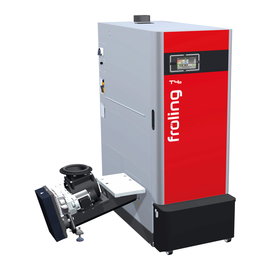
- Page 1 Installation instructions Wood chip boiler T4e 20-180 Translation of original German version of installation instructions for technicians. Read and follow all instructions and safety instructions. All errors and omissions excepted. M1980721_en | Edition 12/07/2021...
-
Page 2: Table Of Contents
Table of contents 1 General ................................. 1.1 About this manual ..........................2 Safety................................2.1 Hazard levels of warnings........................2.2 Qualification of assembly staff ......................2.3 Personal protective equipment for assembly staff ................3 Design Information............................3.1 Overview of standards .......................... 3.1.1 General standards for heating systems .................. - Page 3 Table of contents 6.1 Assembly overview ..........................38 6.2 Accessories supplied ..........................38 6.3 Installing the boiler..........................39 6.3.1 Levelling the boiler ........................39 6.3.2 Installing the stoker unit ......................39 6.3.3 Control the return temperature control..................42 6.3.4 Install line regulating valve (T4e 20-60 - optional) ..............43 6.3.5 Install line regulating valve (T4e 80-180 - optional) ..............
-
Page 4: General
1 | General 1 General Thank you for choosing a quality product from Froling. The product features a state-of- the-art design and conforms to all currently applicable standards and testing guidelines. Please read and observe the documentation provided and always keep it close to the system for reference. -
Page 5: Safety
Safety | 2 2 Safety 2.1 Hazard levels of warnings This documentation uses warnings with the following hazard levels to indicate direct hazards and important safety instructions: DANGER The dangerous situation is imminent and if measures are not observed it will lead to serious injury or death. -
Page 6: Qualification Of Assembly Staff
2 | Safety 2.2 Qualification of assembly staff CAUTION Assembly and installation by unqualified persons: Risk of personal injury and damage to property During assembly and installation: r Observe the instructions and information in the manuals r Only allow appropriately qualified personnel to work on the system Assembly, installation, initial startup and servicing must always be carried out by qualified personnel: - Heating technician / building technician... -
Page 7: Design Information
Design Information | 3 3 Design Information 3.1 Overview of standards Perform installation and commissioning of the system in accordance with the local fire and building regulations. Unless contrary to other national regulations, the latest versions of the following standards and guidelines apply: 3.1.1 General standards for heating systems EN 303-5 Boilers for solid fuels, manually and automatically fed combustion... -
Page 8: Regulations And Standards For Permitted Fuels
3 | Design Information 3.1.4 Regulations and standards for permitted fuels 1. BImSchV First Order of the German Federal Government for the implementation of the Federal Law on Emission Protection (Ordinance on Small and Medium Combustion Plants) in the version published on 26 January 2010, BGBl. -
Page 9: Chimney Connection/Chimney System
Design Information | 3 3.4 Chimney connection/chimney system Connection line to the chimney Measuring port Draught limiter Explosion flap (for automatic boilers) Thermal insulation NOTICE! The chimney must be authorised by a smoke trap sweeper or chimney sweep. The entire flue gas system (chimney and connection) must be laid out as per ÖNORM / DIN EN 13384-1 or ÖNORM M 7515 / DIN 4705-1. -
Page 10: Measuring Port
3 | Design Information 3.4.2 Measuring port Upstream of the measuring port (M) there should be a straight run-in section with a length about twice the diameter (D) of the connection line. Downstream of the measuring port (M) there should be a straight run-out section with a length about the diameter (D) of the connection line. -
Page 11: Combustion Air For Room Air-Dependent Operation
Design Information | 3 3.5 Combustion air for room air-dependent operation Boiler in room air-dependent operation Air extraction system (such as centralised dust extraction system, room ventilation) Under-pressure monitoring system Combustion air supply from outside 3.5.1 Combustion air supply at the installation room The system is operated in open flue mode, i.e. -
Page 12: Simultaneous Operation With Other Air-Drawing Systems
3 | Design Information 3.5.2 Simultaneous operation with other air-drawing systems Where the boiler is operated in room air-dependent mode with simultaneous operation of other air-drawing systems (such as room ventilation), safety devices are necessary: ▪ Air pressure monitor ▪ Flue gas thermostat ▪... -
Page 13: Combustion Air For Room Air-Independent Operation
Design Information | 3 3.6 Combustion air for room air-independent operation Boiler Air extraction system (such as centralised dust extraction system, room ventilation) Combustion air supply from outside (irrespective of ambient air) 3.6.1 Definition of terms There is a central air connection on the back of the boiler. If appropriate supply air and flue gas connections are installed, the boiler can be classified according to EN 15035 as a type C / type C... -
Page 14: Supply Air Line
3 | Design Information 3.6.2 Supply air line NOTICE! Install the combustion air supply (piping) in accordance with the applicable standards Ü "Overview of standards" [} 7] r Connect the supply air line leak-tight to the connection on the boiler Ä Refer to the dimensions of the supply air line connection on the boiler in the Technical Data When dimensioning pipe bends in the supply air line, ensure that: The ratio of the radius of curvature (r) to pipe diameter (d) is greater than 1... -
Page 15: Domestic Hot Water
Design Information | 3 3.7 Domestic hot water Unless contrary to other national regulations, the latest versions of the following standards and guidelines apply: Austria: ÖNORM H 5195 Switzerland: SWKI BT 102-01 Germany: VDI 2035 Italy: UNI 8065 Observe the standards and also follow the recommendations below: r Aim for a pH value of between 8.2 and 10.0. -
Page 16: Pressure Maintenance Systems
3 | Design Information Additional requirements for Switzerland The filling and make-up water must be demineralised (fully purified) ▪ The water must not contain any ingredients that could settle and accumulate in the system ▪ This makes the water non-electroconductive, which prevents corrosion ▪... -
Page 17: Storage Tank
Design Information | 3 3.9 Storage tank NOTICE In principle it is not necessary to use a storage tank for the system to run smoothly. However we recommend that you use the system with a storage tank, as this ensures a continuous supply of fuel in the ideal output range of the boiler. -
Page 18: Technical Information
4 | Technical information 4 Technical information 4.1 Dimensions T4e 20-180 Dimensi Description 20-35 45-60 80-110 130-180 Distance between safety heat exchanger connections Distance between safety heat exchanger connection and front of the boiler Length of particle separator (optional) Distance between stoker and back of the boiler 1165 Boiler length 1170... - Page 19 Technical information | 4 Dimensi Description 20-35 45-60 80-110 130-180 Distance to flow connection (stoker left) Distance between flue gas pipe connection and side of boiler Distance between rear flue gas pipe and side of boiler (stoker left) Distance to return connection (stoker left) Distance between stoker connection and back of the boiler Distance between drainage connection and side of...
-
Page 20: Components And Connections
4 | Technical information 4.2 Components and connections T4e 130-180: Item Description 20 - 60 80-110 130-180 Flue gas pipe connection 149 mm 179 mm 199 mm Boiler flow 1 1/4“ 2“ 2“ Induced draught fan Rear flue gas pipe connection (optional) 149 mm 179 mm 199 mm... -
Page 21: Technical Specifications
Technical information | 4 4.3 Technical specifications 4.3.1 T4e 20 - 35 Description T4e 20 - 35 Nominal output 19.9 25.1 Heat output range 5.95 - 19.9 7.51 - 25.1 9 - 30 10.5 - 35 Electrical connection 400V / 50Hz / fused C16A Power consumption (NL/PL) for boiler without ESP 48 / 39 55 / 39... - Page 22 4 | Technical information Additional data for regulation (EU) 2015/1189 Description Heating up mode automatic Condensing boiler Solid fuel boiler for combined heat and power Combined heating system Ü "Storage tank" [} 17] Storage tank volume Characteristics when operated exclusively with the preferred fuel Useful heat delivered at rated heat output (P 20.4 25.1...
-
Page 23: T4E 45 - 60
Technical information | 4 4.3.2 T4e 45 - 60 Description T4e 45 - 60 Nominal heat output 49.9 Heat output range 13.5 - 45.0 14.9 - 49.9 18,0-60,0 Electrical connection 400V / 50Hz / fused C16A Power consumption (NL/PL) for boiler without ESP 70 / 37 77 / 37 90 / 37... - Page 24 4 | Technical information Additional data for regulation (EU) 2015/1189 Description Heating up mode automatic Condensing boiler Solid fuel boiler for combined heat and power Combined heating system Storage tank volume Ü "Storage tank" [} 17] Characteristics when operated exclusively with the preferred fuel Useful heat delivered at rated heat output (P 43.2 47.8...
-
Page 25: T4E 80 - 110
Technical information | 4 4.3.3 T4e 80 - 110 Description T4e 80 - 110 Rated heat output Heat output range 24 - 80 27 - 90 30 - 100 33 - 110 Electrical connection 400V / 50Hz / fused C16A Power consumption (NL/PL) for boiler without ESP 114 / 47 126 / 51... - Page 26 4 | Technical information Description Auxiliary current consumption at rated heat output 0.114 0.126 0.138 0.138 Auxiliary current consumption at 30% of rated heat 0.047 0.051 0.056 0.057 output (η Auxiliary current consumption in standby mode (P 0.010 0.012 0.015 0.014 Regulation (EU) 2015/1189 –...
-
Page 27: T4E 130 - 150
Technical information | 4 4.3.4 T4e 130 - 150 Description T4e 130 - 150 Rated heat output Output range 39-130 47-140 45-150 Electrical connection 400V / 50Hz / fused C16A Power consumption (NL/PL) for boiler without ESP 137 / 58 137 / 58 136 / 59 wood chips for fuel... - Page 28 4 | Technical information Description Auxiliary current consumption at rated heat output 0.137 0.137 0.136 Auxiliary current consumption at 30% of rated heat 0.058 0.058 0.059 output (η Auxiliary current consumption in standby mode (P 0.014 0.014 0.014 Regulation (EU) 2015/1189 – emissions in [mg/m³] Annual space heating emissions of dust (PM) ≤...
-
Page 29: T4E 160 - 180
Technical information | 4 4.3.5 T4e 160 - 180 Description T4e 160 - 180 Nominal output Output range 48-160 51-170 59-180 Electrical connection 400V / 50Hz / fused C16A Power consumption (NL/PL) for boiler without ESP 136 / 60 136 / 60 136 / 61 wood chips for fuel Power consumption (NL/PL) for boiler with ESP... - Page 30 4 | Technical information Description Auxiliary current consumption at rated heat output 0.136 0.136 0.136 Auxiliary current consumption at 30% of rated heat 0.060 0.060 0.061 output (η Auxiliary current consumption in standby mode (P 0.014 0.013 0.013 Regulation (EU) 2015/1189 – emissions in [mg/m³] Annual space heating emissions of dust (PM) ≤...
-
Page 31: Boiler Data For Planning The Flue Gas System
Technical information | 4 4.3.6 Boiler data for planning the flue gas system Description Flue gas temperature at nominal load °C Flue gas temperature at partial load - volume concentration at nominal load / partial load 12.8 / 11.3 13.3 / 11.8 13.8 / 12.3 Flue gas mass flow at nominal load kg/h... - Page 32 4 | Technical information Description kg/s 0.018 0.020 0.021 0.023 Required feed pressure at nominal load mbar 0.05 Required feed pressure at partial load mbar 0.02 Maximum permissible feed pressure mbar Flue pipe diameter Description Flue gas temperature at nominal load °C Flue gas temperature at partial load - volume concentration at nominal load / partial load...
-
Page 33: Transport And Storage
Transport and storage | 5 5 Transport and storage 5.1 Delivery configuration The boiler and associated components are delivered on a pallet. Item Description Unit 20-35 45-60 80-110 130-18 Length 1550 1680 1870 2180 Width Height 1730 1930 1995 2095 Weight of the components: Boiler 1060... -
Page 34: Positioning
5 | Transport and storage 5.3 Positioning NOTICE Damage to components if handled incorrectly r Follow the transport instructions on the packaging r Transport components with care to avoid damage r Protect the packaging against damp conditions r Pay attention to the pallet's centre of gravity when lifting r Position a fork-lift or similar lifting device at the pallet and bring in the components If the boiler cannot be brought in on the pallet: r Remove the cardboard and take the boiler off the pallet... -
Page 35: Positioning At The Installation Site
Transport and storage | 5 Also for T4e 80-110: r Disconnect the plug connection (A) from the Lambda probe cable r Protect the cable from damage r Hang the crane hook on the two eye bolts in the flue gas collection chamber and bring in the boiler 5.4 Positioning at the installation site 5.4.1 Remove boiler from pallet... - Page 36 5 | Transport and storage r Remove securing devices used during transportation on the left and right side of the boiler r Pull out floor insulation r Lift boiler from pallet TIP: use Froling’s KHV 1400 boiler lifting system to help remove the pallet! r Position a fork-lift or similar lifting device with a suitable load-bearing capacity at the base frame r Lift it and transport it to the intended position...
-
Page 37: Operating And Maintenance Areas Of The Equipment
Transport and storage | 5 5.4.2 Operating and maintenance areas of the equipment ▪ The system should generally be set up so that it is accessible from all sides allowing quick and easy maintenance. ▪ Regional regulations regarding necessary maintenance areas for inspecting the chimney should be observed in addition to the specified distances! ▪... -
Page 38: Assembly
6 | Assembly 6 Assembly 6.1 Assembly overview Ash container Stoker unit Boiler documents (4 items) Tread plate Floor insulation Line regulating valve (optional) 6.2 Accessories supplied (T4e 20-60) (T4e 80-180) Furnace tool with bracket Key for door mountings and WOS cover Socket wrench AF 13 Cleaning brush 24 x 50 x 1200 M1980721_en | Installation instructions Wood chip boiler T4e 20-180... -
Page 39: Installing The Boiler
Assembly | 6 6.3 Installing the boiler 6.3.1 Levelling the boiler r Lift the boiler using an appropriate lifting device r Position a Sylomer pad under the boiler base Ä Sylomer pads prevent the transmission of noise to the ground r Carefully release the lifting device and check that the boiler is level r If necessary, level the boiler using load-bearing pads 6.3.2 Installing the stoker unit... - Page 40 6 | Assembly r Position seal (A) on the connection flange r Move the stoker unit towards the boiler and insert into the connection flange at the two lock bolts (B) Ä Pay attention to the ignition element when positioning the stoker unit! r Adjust the height using the adjustable base (C) as required r Secure the stoker unit to the connection flange using the previously removed screws M1980721_en | Installation instructions Wood chip boiler T4e 20-180...
- Page 41 Assembly | 6 r Remove the bracket. It is no longer needed r Assemble the entire discharge system r Lay the cable via the side panel to the controller box for the boiler Ä Geared motor stoker, geared motor feed system, cable limit switch gravity shaft cover r Attach the previously removed shutter masks to the stoker duct r Pre-assemble four hexagonal screws on the stoker duct...
-
Page 42: Control The Return Temperature Control
6 | Assembly 6.3.3 Control the return temperature control r Remove both back panels r Tighten all of the connections on the return temperature control using a pipe wrench Ä Connections may have loosened during transport. Ä IMPORTANT: Before and after filling the system with heated water, check the seal of the screw connections on the return temperature control Return temperature control left r Set the knob on the housing of the mixing drive to manual mode (A) -
Page 43: Install Line Regulating Valve (T4E 20-60 - Optional)
Assembly | 6 Return temperature control right r Set the knob on the housing of the mixing drive to manual mode (A) r Turn the mixing drive clockwise until it stops Ä The mixer valve completely closes off the system return r Turn the mixing drive counter clockwise until it stops Ä... -
Page 44: Install Line Regulating Valve (T4E 80-180 - Optional)
6 | Assembly r Remove pipe section r Seal line regulating valve instead Ä IMPORTANT: Pay attention to direction of flow. The arrow on the line regulating valve must point downward! r Fit both rear panels r Remove the perforation on the rear cover plate Ä... -
Page 45: Adjusting The Height Of The Ash Container
Assembly | 6 r Remove the pipe section and ball valve r Seal line regulating valve instead Ä IMPORTANT: Pay attention to direction of flow. Arrow (A) must point downward! r Install centre back panel r Remove the perforation on the cover plate Ä... -
Page 46: Fitting The Thermal Discharge Valve (T4E 130-180)
6 | Assembly 6.3.7 Fitting the thermal discharge valve (T4e 130-180) r Slide the capillary tube and metal tube insulation into the immersion sleeve and secure with slotted screw r Connect the thermal discharge safety valve in accordance with all current directives, Ü... -
Page 47: Hydraulic Connection
Assembly | 6 6.4 Hydraulic connection T4e 130-180: CAUTION: The flow and return connections are located on the stoker side Thermal discharge valve (T4e 130-180) ▪ The thermal discharge safety device must be connected in accordance with ÖNORM/ DIN EN 303-5 and as shown in the diagram above ▪... -
Page 48: Electrical Connection
6 | Assembly 6.5 Electrical connection DANGER When working on electrical components: Risk of electrocution! When work is carried out on electrical components: r Always have work carried out by a qualified electrician r Observe the applicable standards and regulations Ä... -
Page 49: Board Overview
Assembly | 6 6.5.1 Board overview T4e 20-60 Item Description Item Description Main switch Hydraulic module High-limit thermostat (STL) Core module Service interface Wood chip module Device connection terminal Plug power pack M1980721_en | Installation instructions Wood chip boiler T4e 20-180... -
Page 50: Laying Cables
6 | Assembly T4e 80-180 Item Description Item Description Main switch Core module High-limit thermostat (STL) Wood chip module Service interface Plug power pack Device connection terminal Digital module (optional) Hydraulic module 6.5.2 Laying cables r Remove the insulating cover and thermal insulation r Remove the retaining screw and contact washer from the controller cover M1980721_en | Installation instructions Wood chip boiler T4e 20-180... -
Page 51: Mains Connection
Assembly | 6 r Slide the controller cover backwards and lift off r Wire all the components via cable duct (A) in the side panel to the controller box Ä Drive for feed screw / discharge system Ä Limit switch on gravity shaft cover (not pre-wired) r Plug the following components into the cable that is already in place Ä... -
Page 52: Potential Equalisation
6 | Assembly 6.5.4 Potential equalisation r The potential equalisation on the boiler base must comply with current directives, regulations and standards. M1980721_en | Installation instructions Wood chip boiler T4e 20-180... -
Page 53: Final Installation Steps
Assembly | 6 6.6 Final installation steps r Place the controller cover on the controller box and slide forward r Attach the controller cover with retaining screw and contact washers r Put on the heat exchanger cover and attach using star-shaped screws r Put on the insulating cover and thermal insulation Ä... -
Page 54: Insulate The Connection Line
6 | Assembly 6.6.1 Insulate the connection line When using the optionally available thermal insulation supplied by Fröling GesmbH, perform the following steps: r Cut the half shells of thermal insulation to length and lay them on the connection line r Create an opening for access to the measuring port r Apply protective foil at the projecting lugs r Glue the half shells to each other... -
Page 55: Start-Up
Start-up | 7 7 Start-up 7.1 Before commissioning / configuring the boiler The boiler must be configured to the heating system during initial start-up! NOTICE Optimum efficiency and efficient, low-emission operation can only be guaranteed if the system is set up by trained professionals and the standard factory settings are observed. -
Page 56: Decommissioning
8 | Decommissioning 8 Decommissioning 8.1 Mothballing The following measures should be taken if the boiler is to remain out of service for several weeks (e.g. during the summer): r Clean the boiler thoroughly and close the doors fully If the boiler is to remain out of service during the winter: r Have the system completely drained by a qualified technician Ä... - Page 57 Notes M1980721_en | Installation instructions Wood chip boiler T4e 20-180...
- Page 58 M1980721_en | Installation instructions Wood chip boiler T4e 20-180...
- Page 59 M1980721_en | Installation instructions Wood chip boiler T4e 20-180...
- Page 60 Manufacturer’s address Froling srl Froling SARL Fröling Heizkessel- und Zweigniederlassung Behälterbau GesmbH Aschheim Industriestraße 12 Max-Planck-Straße 6 Via J. Ressel 2H 1, rue Kellermann A-4710 Grieskirchen 85609 Aschheim I-39100 Bolzano (BZ) F-67450 Mundolsheim +43 (0) 7248 606 0 +49 (0) 89 927 926 0 +39 (0) 471 060460 +33 (0) 388 193 269 info@froeling.com...
Need help?
Do you have a question about the T4e 20-35 and is the answer not in the manual?
Questions and answers