Table of Contents
Advertisement
Quick Links
Advertisement
Table of Contents

Related Manuals for Fröling S1 Turbo 15-20 (F)


Summary of Contents for Fröling S1 Turbo 15-20 (F)
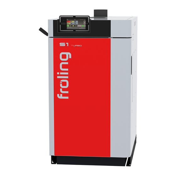
- Page 1 Operating instructions Firewood boiler S1 Turbo 15-20 (F) Translation of original German version of operating instructions for operators. Read and follow all instructions and safety instructions. All errors and omissions excepted. B1490623_en | Edition 04/09/2023...
-
Page 2: Table Of Contents
Table of contents 1 General ................................. 1.1 Operating principle ..........................1.2 S1 Turbo Product Overview ........................2 Safety................................2.1 Hazard levels of warnings ........................2.2 Pictograms used ........................... 2.3 General safety information ........................2.4 Permitted uses ............................2.4.1 The Clean Air Act 1993 and Smoke Control Areas..............2.4.2 Permitted fuels ........................... - Page 3 Table of contents 4.7.5 Change desired DHW tank temperature..................42 4.7.6 One-time extra loading of an individual DHW tank ..............42 4.7.7 One-time extra loading of all existing DHW tanks..............42 4.7.8 Set the heating curve of a heating circuit................... 43 4.7.9 Change room temperature (heating circuit without room temperature sensor) ......
-
Page 4: General
1 | General 1 General Thank you for choosing a quality product from Froling. The product features a state-of- the-art design and conforms to all currently applicable standards and testing guidelines. Please read and observe the documentation provided and always keep it close to the system for reference. -
Page 5: S1 Turbo Product Overview
General | 1 1.2 S1 Turbo Product Overview Insulated door Cladding plates Fuel loading door Servo-motor/manual adjuster Combustion chamber door with inspection glass Combustion chamber Controller cover WOS (Efficiency Optimisation System) Lambdatronic S 3200 controller, Induced draught fan Ü "Overview of the touch display" [} 33] Carbonisation gas duct flap Lever of the heat exchanger cleaner (WOS system) B1490623_en | Operating instructions Firewood boiler S1 Turbo 15-20 (F) -
Page 6: Safety
2 | Safety 2 Safety 2.1 Hazard levels of warnings This documentation uses warnings with the following hazard levels to indicate direct hazards and important safety instructions: DANGER The dangerous situation is imminent and if measures are not observed it will lead to serious injury or death. -
Page 7: Pictograms Used
Safety | 2 2.2 Pictograms used The following symbols are used in the documentation and/or on the boiler to show what is required and forbidden and to give warnings. In accordance with the Machinery Directive, signs fitted directly within the danger area of the boiler indicate immediate hazards or safety procedures. -
Page 8: General Safety Information
2 | Safety 2.3 General safety information DANGER If the device is used incorrectly: Incorrect use of the system can cause severe injury and damage. When operating the system: r Observe the instructions and information in the manuals r Observe the details on procedures for operation, maintenance and cleaning, as well as troubleshooting in the respective manuals. -
Page 9: The Clean Air Act 1993 And Smoke Control Areas
Safety | 2 operator will then be fully responsible for the declaration of conformity according to the valid guideline(s) for the product and will need to issue a corresponding declaration for the device. This person will then assume all of the rights and responsibilities of a manufacturer. -
Page 10: Fuels Permitted Under Certain Conditions
2 | Safety Storage time dependent upon water content Wood type Water content 15 – 25% less than 15 Storage in heated and ventilated room Soft wood (e.g. approx. from 1 year (approx. 20°C) spruce) 6 months Hardwood (e.g. 1 – 1.5 years from 2 years beech) Outdoor storage (protected from elements,... -
Page 11: Non-Permitted Fuels
Safety | 2 2.4.4 Non-permitted fuels The use of fuels other than those defined in the "Permitted fuels" section, and particularly the burning of refuse, is not permitted NOTICE In case of use of non-permitted fuels: Burning non-permitted fuels increases the cleaning requirements and leads to a build-up of aggressive sedimentation and condensation, which can damage the boiler and also invalidates the guarantee! Using non-standard fuels can also lead to serious problems with combustion! -
Page 12: Safety Devices
2 | Safety 2.7 Safety devices THERMAL DISCHARGE VALVE (protection against overheating) The thermal discharge valve opens at approx. 100°C and feeds cold water to the safety heat exchanger to lower the boiler temperature SAFETY VALVE (protection against overheating/excess pressure) When the boiler pressure reaches a maximum of 3 bar, the safety valve opens and the heated water is blown off in the form of steam. -
Page 13: Residual Risks
Safety | 2 2.8 Residual risks WARNING When the main switch is switched off in heating mode: The boiler is placed in an uncontrolled state. Any resulting boiler malfunctions can cause serious injury and damage. Therefore: r Allow the fire to burn out completely and let the boiler cool, only then switch off the main switch. -
Page 14: Emergency Procedure
2 | Safety WARNING If you open the combustion chamber door/fuel loading door during operation: This could result in injury, damage or flue gas generation! Therefore: r Never open the combustion chamber door during operation r The fuel loading door must be kept closed during operation and may only be opened briefly during reloading intervals NOTICE Automatic ignition set incorrectly or not carried out... -
Page 15: Smell Of Flue Gas
Safety | 2 2.9.2 Smell of flue gas DANGER If you smell flue gas in the boiler room: Inhaling toxic flue gas can potentially be fatal! If you smell flue gas in the room where the boiler is installed: r Keep all the doors on the boiler closed r Ventilate the room where the boiler is installed r Close the fire door and doors to living areas r Allow the fire to burn out completely and let the boiler cool... -
Page 16: Power Failure / Induced Draught Fan Failure
2 | Safety 2.9.3 Power failure / induced draught fan failure A power failure, among others, can be identified based on the following points: ▪ Display remains dark despite touching it ▪ LED status does not flash / light up ▪... -
Page 17: Notes For Operating A Heating System
Notes for operating a heating system | 3 3 Notes for operating a heating system Carrying out modifications to the system and changing or disabling safety equipment is prohibited. Always comply with all fire, building and electrical regulations when installing or operating the system, in addition to following the operating instructions and mandatory regulations that apply in the country in which the tank is operated. -
Page 18: Combustion Air
3 | Notes for operating a heating system 3.3 Combustion air Boiler in room air-dependent operation Air extraction system (such as centralised dust extraction system, room ventilation) Under-pressure monitoring system Combustion air supply from outside 3.3.1 Combustion air supply at the installation room The system is operated in open flue mode, i.e. -
Page 19: Simultaneous Operation With Other Air-Drawing Systems
Notes for operating a heating system | 3 3.3.2 Simultaneous operation with other air-drawing systems Where the boiler is operated in room air-dependent mode with simultaneous operation of other air-drawing systems (such as room ventilation), safety devices are necessary: ▪ Air pressure monitor ▪... -
Page 20: Domestic Hot Water
3 | Notes for operating a heating system 3.4 Domestic hot water Unless contrary to other national regulations, the latest versions of the following standards and guidelines apply: Austria: ÖNORM H 5195 Switzerland: SWKI BT 102-01 Germany: VDI 2035 Italy: UNI 8065 Observe the standards and also follow the recommendations below: r Aim for a pH value of between 8.2 and 10.0. -
Page 21: Pressure Maintenance Systems
Notes for operating a heating system | 3 Additional requirements for Switzerland The filling and make-up water must be demineralised (fully purified) ▪ The water must not contain any ingredients that could settle and accumulate in the system ▪ This makes the water non-electroconductive, which prevents corrosion ▪... -
Page 22: Return Lift
3 | Notes for operating a heating system 3.6 Return lift If the hot water return temperature is below the minimum return temperature, some of the hot water outfeed will be mixed in. NOTICE Risk of dropping below dew point/condensation formation if operated without return temperature control. -
Page 23: Operating The System
Operating the System | 4 4 Operating the System 4.1 Assembly and initial startup Assembly, installation and initial startup of the boiler must only be carried out by qualified staff, and these procedures are described in the accompanying assembly instructions. NOTICE! See assembly instructions for theS1 Turbo NOTICE Optimum efficiency and efficient, low-emission operation can only be guaranteed if the... -
Page 24: Switching On The Power Supply
4 | Operating the System 4.2 Switching on the power supply r Turn on the main switch Ä There is voltage at all of the boiler's components Ä When the control has completed the system start, the boiler is ready for operation 4.3 Before heating up the boiler 4.3.1 Clean the heat exchanger pipes r Pull the lever of the cleaning system several times before heating up... -
Page 25: Reloading Intervals When Operating With Storage Tank
Operating the System | 4 4.3.3 Reloading intervals when operating with storage tank Reloading intervals and amounts should be determined exclusively according to the storage tank for efficient and environmentally-friendly heating. If the information for the storage tank appears on the basic display, the symbol will show Ü... -
Page 26: Reload Quantity Calculation
4 | Operating the System 4.3.4 Reload quantity calculation The reload quantity calculation is used to display on the control how much firewood is required to refill the boiler based on the current storage tank fill level. It does not take into account boiler efficiency, pipe losses and the energy required to heat the boiler and heating system. -
Page 27: Determining The Right Amount Of Fuel
Operating the System | 4 4.3.5 Determining the right amount of fuel The amount of fuel added should allow the storage tank to be constantly heated to the max. storage tank temperature (= boiler target temperature). Please note that the amount to reload also depends on the type of fuel. -
Page 28: Reloading Intervals When Operating Without Storage Tank Or If The Storage Tank Is Too Small
4 | Operating the System Fuel table The table below shows a selection of wood types with the corresponding energy content depending on the water content: Wood type Energy content with water content [kWh/kg] w = 15% w = 20% w = 25% Spruce Pine... -
Page 29: Filling The Boiler With Firewood
Operating the System | 4 4.4 Filling the boiler with firewood NOTICE Fill fuel loading chamber for later manual / automatic ignition Premature self-ignition of the firewood by residual heat / temperature of the combustion chamber possible Therefore: r Completely remove residual embers from the combustion chamber r Allow the combustion chamber to cool down r An ash layer up to the middle row of holes in the combustion chamber guards facilitates the ignition process... -
Page 30: Heat Up Firewood Manually
4 | Operating the System Heat up firewood manually / with automatic ignition 1. First layer of small pieces of split firewood – Length approx. 50 cm – Parts of the burn-out opening (A) in the grating must remain clear 2. -
Page 31: Heat Up The Firewood With Automatic Ignition
Operating the System | 4 Ä Once successfully ignited: switch induced draught fan back on by tapping “Induced draught ON” r Leave the fuel loading door open for approximately 5 minutes Ä A bed of embers forms Ä Wait for the message on the boiler display to close the pre-heating chamber door 4.6 Heat up the firewood with automatic ignition NOTICE Automatic ignition set incorrectly or not carried out... - Page 32 4 | Operating the System In submenu (A) set the criteria for starting the ignition: Setting Description Date and time The ignition process starts at the set time. When “daily” is selected, the ignition process starts at the set time every day.
-
Page 33: Operate The Boiler Using The Touch Display
Operating the System | 4 4.7 Operate the boiler using the touch display 4.7.1 Overview of the touch display Display of freely selectable information Ü "Select information displays" [} 39] Display and switch the current user level Ü "Lock display/switch user level" [} 46] Display and change the current date/time Ü... - Page 34 4 | Operating the System USB interface for software update (➾ see operating instructions for the boiler controller) NOTICE! USB interface is for service purposes only and must not be used for charging devices or for PC connections! Status display The status display indicates the system’s operating status: ▪...
- Page 35 Operating the System | 4 Display icons for froeling-connect/remote control The icons for connection status and remote control are displayed at the top left of the touch display. Tap on these icons to open the “Connection Centre”. In the menu, the connection to froeling-connect as well as the remote control (switching on and off by external users) is activated/deactivated Status to froeling-connect...
- Page 36 4 | Operating the System Navigation within the system menu The system menu shows the menus available depending on the user level and the system configuration. Use the right and left arrows to navigate to the individual menus. Tap the corresponding icon to open the menu. Within the individual menus, the status display is shown with current values.
- Page 37 Operating the System | 4 Changing parameters If there is a “pencil” symbol next to a parameter text, the parameter can be edited. Depending on the type of parameter, it can be edited using the numeric keypad or by selecting from a list and then tapping on the “Confirm” symbol. Numeric keypad Dropdown list Change time window...
- Page 38 4 | Operating the System Quick menu The quick menu provides different functions depending on the system configuration and system status. Icon Description Language selection Sets the desired system language: Deutsch – English – Francais – Italiano – Slovenski – Cesky – Polski – Svenska – Espanol –...
-
Page 39: Select Information Displays
Operating the System | 4 4.7.2 Select information displays Tapping on the randomly selectable information displays in the basic display opens the respective menu. The following options are available depending on the system configuration: Menu Selection Icon Description Boiler Empty ash box in Display of the remaining heating hours until the message “Ash box full, please empty”... - Page 40 4 | Operating the System When using more than two store sensors, it is possible to have an information display with storage tank temperatures in accordance with the number of sensors. An information display that spans two areas is used. B1490623_en | Operating instructions Firewood boiler S1 Turbo 15-20 (F)
-
Page 41: Change Boiler Mode
Operating the System | 4 4.7.3 Change boiler mode Depending on the type of boiler, there are several modes available which can be changed directly in the basic display of the touch display. Mode Icon Description Automatic Supply heating circuits and domestic hot water tanks with heat according to the selected heating times. -
Page 42: Change Desired Dhw Tank Temperature
4 | Operating the System 4.7.5 Change desired DHW tank temperature r Tap the information display for the desired DHW tank r Adjust the temperature setpoint by tapping on “+” or “-” NOTICE! If this selection is not configured in the information display in the basic display, open the components in the system menu. -
Page 43: Set The Heating Curve Of A Heating Circuit
Operating the System | 4 4.7.8 Set the heating curve of a heating circuit A flow temperature is calculated using the heating curve of the heating circuit depending on the outside air temperature and the two adjustable parameters “flow temperature at -10°C outside air temperature”... -
Page 44: Change Room Temperature (Heating Circuit Without Room Temperature Sensor)
4 | Operating the System 4.7.9 Change room temperature (heating circuit without room temperature sensor) Situation Effect Room temperature generally too low Move heating curve up in parallel. Increase both points on the heating curve by the same temperature level. (see figure 1) Room temperature on cold days too low, OK on Change the slope of the heating curve. -
Page 45: Change Room Temperature (Heating Circuit With Room Temperature Sensor)
Operating the System | 4 4.7.10 Change room temperature (heating circuit with room temperature sensor) r Tap information display of the desired heating circuit r Tap “+” or “-” to adjust the desired room temperature NOTICE! If this selection is not configured in the information display in the basic display, open the components in the system menu. -
Page 46: Lock Display/Switch User Level
4 | Operating the System 4.7.12 Lock display/switch user level For safety reasons, individual parameters are only visible at specific operating levels. To change to another level it is necessary to enter the relevant user code. r Tap on the icon for the user level in the upper area of the basic display and enter the code. -
Page 47: Configure The Holiday Program
Operating the System | 4 4.7.14 Configure the holiday program Setting a start and end date in the holiday program determines a time period in which an active heating circuit is regulated for the set setback temperature and in which an activated boiler is not loaded. -
Page 48: Reloading Firewood
4 | Operating the System Tap the “suitcase” icon to prematurely end the holiday program. The boiler then switches to the previously activated mode (“water tap” symbol = domestic hot water, “water tap/ radiator” symbol = automatic). 4.8 Reloading firewood WARNING Touching hot surfaces behind the insulated door can cause burns! -
Page 49: Switching Off The Power Supply
Operating the System | 4 WARNING Opening the fuel loading door can cause injury, damage and smoke! r Open the fuel loading door slowly and with care r Close the fuel loading door again immediately after checking/reloading r Open the fuel loading door slowly and check the fuel If the fuel in the boiler has burnt down: r Refill with fuel Ü... -
Page 50: Checking The Ash Level In The Boiler
4 | Operating the System 4.10 Checking the ash level in the boiler NOTICE Cracks in the combustion chamber may occur during operation. If the fireclay elements and the surrounding seals remain in their original position, existing cracks do not represent a malfunction! 4.10.1 Removing ash Recommendation: Do not remove the ash in the combustion chamber each time you heat up the boiler, but rather only when the middle row of holes (2) in the combusion... -
Page 51: Cleaning The Combustion Grate
Operating the System | 4 4.10.2 Cleaning the combustion grate r Open the fuel loading door and remove the combustion grate r Remove ash deposits from the combustion grate and secondary air inlets (A) B1490623_en | Operating instructions Firewood boiler S1 Turbo 15-20 (F) -
Page 52: Servicing The System
5 | Servicing the system 5 Servicing the system 5.1 General information on servicing DANGER When working on electrical components: Risk of electrocution! When work is carried out on electrical components: r Always have work carried out by a qualified electrician r Observe the applicable standards and regulations Ä... -
Page 53: Required Tools
Servicing the system | 5 5.2 Required tools The following tools are required for carrying out cleaning and maintenance work: Included in delivery: Furnace tool with bracket Spanner for door mountings Ash shovel Socket wrench AF 13 Ash drawer Cleaning brush (30x20) for cleaning the carbonisation gas duct Cleaning brush (80x60) for cleaning the heat exchanger Not included: Spanner or box wrench AF 10... -
Page 54: Maintenance Work By The Operator
5 | Servicing the system 5.3 Maintenance work by the operator r Regular cleaning of the boiler extends its life and is a basic requirement for smooth running. r Recommendation: Use an ash vacuum for cleaning. Reassemble the boiler components dismantled during maintenance in the reverse order after the work has been completed.. -
Page 55: Periodic Inspection And Cleaning
Servicing the system | 5 5.3.2 Periodic inspection and cleaning The boiler must be inspected and cleaned at appropriate intervals depending on the operating hours and fuel quality. Inspection and cleaning must be repeated after not more than 1500 operating hours or at least once a year. - Page 56 5 | Servicing the system r Take off the cladding plates and clean them r Check the primary air openings (A) inside the boiler for unobstructed air flow and clean if necessary r Unhinge the front air guide plate r Clean the air openings (A) in the guide plate r Check the air inlet inside the boiler for unobstructed air flow and clean if necessary B1490623_en | Operating instructions Firewood boiler S1 Turbo 15-20 (F)
- Page 57 Servicing the system | 5 Cleaning the flue gas temperature sensor r Remove the insulating cover and thermal insulation r Release the retaining screw and remove the flue gas temperature sensor from the flue gas pipe r Wipe the flue gas temperature sensor with a clean cloth r Push in the flue gas temperature sensor until about 20 mm of the sensor remains protruding from the bushing and secure with fixing screw Cleaning the flue gas pipe...
- Page 58 5 | Servicing the system Checking the draught controller flap r Check that the draught regulation damper moves freely and clean the flap bearing if necessary Cleaning the induced draught fan r Unplug the connection cable of the induced draught fan r Remove the cover plate for ID fan and induced draught fan on the back of the boiler r Check the seal for damage and replace if necessary r Clean the fan wheel from the inside out using a soft brush or paint brush...
- Page 59 Servicing the system | 5 Clean the heat exchanger pipes r Remove controller cover and side thermal insulation r Undo the screws and remove the cleaning lid Ä Use the socket wrench provided r Open the insulated door r Loosen the screws on the cover plate and pull up to unhook the cover plate r Push the WOS lever down and remove it from the shaft r Remove both tube clips from the WOS stay tube r Pull the shaft forward and out...
- Page 60 5 | Servicing the system r Clean the heat exchanger pipes (A) with the brush provided Ä Push the cleaning brush all the way through before pulling it up Ä The bristles cannot be turned in the pipe. r Clean the side passage (B) to the flue gas pipe Ä...
- Page 61 Servicing the system | 5 Positioning the doors The example below shows how to position the fuel loading door. The procedure is the same for positioning the combustion chamber door! r Loosen the lock nuts on the locking cams at the top and bottom r Close the door Ä...
-
Page 62: Maintenance Work By Technicians
5 | Servicing the system 5.4 Maintenance work by technicians CAUTION If maintenance work is carried out by untrained personnel: Risk of personal injury and damage to property! The following applies for maintenance: r Observe the instructions and information in the manuals r Only allow appropriately qualified personnel to work on the system Only qualified staff are permitted to carry out maintenance work in this chapter: ▪... - Page 63 Servicing the system | 5 r Carefully remove the Lambda probe (1), adapter (2) and plastic bushing (3) Ä Pay attention to the cables of the Lambda probe! r Carefully remove impurities from the measuring ports with a fine brush and ash vacuum Ä...
-
Page 64: Emissions Measurement By Chimney Sweep Or Regulatory Body
5 | Servicing the system 5.5 Emissions measurement by chimney sweep or regulatory body Various legal regulations stipulate that heating systems must be inspected periodically. In Germany this is regulated by the First Federal Emissions Protection Ordinance (BimSchV) in the last amended version, and in Austria by various state laws. The following minimum requirements must be met by the operator of the system for a successful measurement: r Thoroughly clean the boiler 2 heating days (1 heating day = 1 day during which the... -
Page 65: Create The Measurement Conditions And Perform The Measurement
Servicing the system | 5 5.5.2 Create the measurement conditions and perform the measurement r Fill the boiler approx. 1/4 full with small pieces of split wood in accordance with the operating instructions and heat up Ä TIP: The smaller the wood is split, the better and faster the bed of embers forms r Ensure that the operating conditions are fulfilled Ä... -
Page 66: Replacement Parts
5 | Servicing the system 5.6 Replacement parts With Froling original replacement parts in your system, you are using parts that match perfectly. As the parts fit together so well, installation times are shortened and a long service life is maintained. NOTICE Installing non-original parts will invalidate the guarantee. -
Page 67: Troubleshooting
Troubleshooting | 6 6 Troubleshooting 6.1 Carbonisation gas duct flap is stiff Error characteristics Possible cause Elimination of error Carbonisation gas duct flap is Flap guide blocked Check the area under the stiff inspection cover for dirt and deposits and clean if necessary Little or no draught through the Flap cannot be closed due to combustion chamber when the... -
Page 68: Behaviour Of System After A Power Failure
6 | Troubleshooting 6.2.1 Behaviour of system after a power failure When the power supply has been restored, the boiler returns to the previous mode and is controlled according to the specified program. r After a power failure, check whether the STL (high-limit thermostat) has tripped. r Keep the doors of the boiler closed during and after the power failure, at least until the induced draught fan automatically starts up again. - Page 69 Troubleshooting | 6 r Remove the cover plate with servo-motor Ä Note the servo-motor cable! r Undo the four screws on the base plate as shown r Fit the air volume throttle plate using the removed screws so that “SH W<15” can be seen in the top part r Fit the cover plate with servo-motor r Close the fuel loading door and combustion chamber door...
-
Page 70: Excessive Temperature
6 | Troubleshooting 6.4 Excessive temperature The high-limit thermostat (STL) switches off the blower fan at a maximum boiler temperature of 105 °C. The pumps continue to run. Once the temperature falls below approx. 75°C, the STL can be reset mechanically. r Unscrew the cap on the STB (high-limit thermostat) r Unlock the STL by pressing with a screwdriver 6.5 Faults with fault message... -
Page 71: Procedure For Fault Messages
Troubleshooting | 6 6.5.1 Procedure for fault messages If a fault occurs on the boiler, it will be shown on the display. If the fault is acknowledged, although it has not been rectified, the window with the associated fault can be reopened as follows: Open error display Current fault list System menu... - Page 72 Manufacturer’s address Fröling Heizkessel- und Zweigniederlassung Froling srl Froling SARL Behälterbau GesmbH Aschheim Industriestraße 12 Max-Planck-Straße 6 Via J. Ressel 2H 1, rue Kellermann A-4710 Grieskirchen 85609 Aschheim I-39100 Bolzano (BZ) F-67450 Mundolsheim +43 (0) 7248 606 0 +49 (0) 89 927 926 0 +39 (0) 471 060460 +33 (0) 388 193 269 info@froeling.com...
Need help?
Do you have a question about the S1 Turbo 15-20 (F) and is the answer not in the manual?
Questions and answers