Chauvin Arnoux F205 User Manual
Clamp multimeter
Hide thumbs
Also See for F205:
- Start manual (2 pages) ,
- Start manual (73 pages) ,
- Quick start manual (76 pages)
Table of Contents
Advertisement
Advertisement
Table of Contents

Subscribe to Our Youtube Channel
Related Manuals for Chauvin Arnoux F205


Summary of Contents for Chauvin Arnoux F205
- Page 1 CLAMP MULTIMETER F205 EN G L I S H User’s manual...
-
Page 2: Table Of Contents
Clamp Multimeter F205 English CONTENTS PRESENTATION ......................8 THE SWITCH ........................9 THE KEYS OF THE KEYPAD ..................10 THE DISPLAY UNIT ....................... 11 1.3.1 The symbols of the display unit ..............11 1.3.2 Measurement capacity exceeded (O.L) ............13 THE TERMINALS ...................... - Page 3 English Clamp Multimeter F205 3.11 POWER MEASUREMENTS W, VA, AND PF ............. 27 3.11.1 Measurement of single-phase power ............28 3.11.2 Balanced three-phase power measurement ..........28 “DIRECTION OF ROTATION OF THE PHASES” OR “ORDER OF THE PHASES” 3.12 MODE ..........................
- Page 4 Clamp Multimeter F205 English VARIATIONS IN THE DOMAIN OF USE ..............48 MAINTENANCE ....................... 49 CLEANING ........................49 REPLACEMENT OF THE BATTER ................49 METROLOGICAL CHECK .................... 49 REPAIR ..........................49 WARRANTY ......................50 DELIVERY CONDITION ..................50...
- Page 5 English Clamp Multimeter F205 You have just acquired an F205 clamp multimeter and we thank you. For best results from your device : • read this user manual attentively, • observe the precautions for its use. Meanings of the s ymbols us ed on the devic e Danger.
- Page 6 Clamp Multimeter F205 English PRECAUTIONS FOR USE This device complies with safety standards IEC-61010-1 and 61010-2-032 for voltages of 1000V in category III or 600V in category IV at an altitude OF less than 2000m, indoors, with a degree of pollution not exceeding 2.
- Page 7 English Clamp Multimeter F205 When handling the test probes, crocodile clips, and clamp ammeters, keep your fingers behind the physical guard. As a safety measure, and to avoid repeated overloads on the inputs of the device, we recommend performing configuration operations only when the device is disconnected from all dangerous voltages.
-
Page 8: Presentation
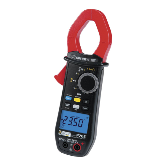
Clamp Multimeter F205 English PRESENTATION The F205 is a professional electrical measuring instrument that combines the following functions: Current measurement; Measurement of inrush current / overcurrent (True-Inrush); Voltage measurement; Frequency measurement; Measurement of level of harmonics (THD) ... -
Page 9: The Switch
English Clamp Multimeter F205 THE SWITCH The switch has six positions. To access the , functions, set the switch to the desired function. Each setting is confirmed by an audible signal. The functions are described in the table below. Figure 2 : the switch... -
Page 10: The Keys Of The Keypad
Clamp Multimeter F205 English THE KEYS OF THE KEYPAD Here are the six keys of the keypad : Figure 3 : the keys of the keypad Item Function See § Storage of values, disabling of display Zero correction A 3.9.2... -
Page 11: The Display Unit
English Clamp Multimeter F205 THE DISPLAY UNIT Here is the display unit of the clamp multimeter: Figure 4 : the display unit Item Function See § Display of the modes selected (keys) Display of the measurement value and unit 3.12... - Page 12 Clamp Multimeter F205 English Storage of the values and hold of the display Maximum RMS value Minimum RMS value Peak+ Maximum peak value Peak- Minimum peak value Balanced total three-phase power measurement Volt Hertz Watt Ampere Percentage Ω Milli- prefix...
-
Page 13: Measurement Capacity Exceeded (O.l)
English Clamp Multimeter F205 1.3.2 Measurement capacity exceeded (O.L) The O.L (Over Load) symbol is displayed when the display capacity is exceeded. THE TERMINALS The terminals are used as follows: Item Function Cold terminal (COM) Hot terminal (+) Figure 5 : the terminals 2 THE KEYS The keys of the keypad respond differently to short, long, and sustained presses. -
Page 14: Key (Second Function)
Clamp Multimeter F205 English perform automatic compensation of the resistance of the leads (see also § 3.6.1) ; perform an automatic zero correction in A et W (see also § AC+DC AC+DC 3.9.2) Remark : the key is invalid for the “Indication of order of phases” function. -
Page 15: Key
English Clamp Multimeter F205 -to cycle through the Ω and diode test modes and to return to the continuity test - to reset the measurement process for the “indicator of order of rotation of the phases” function. Long (>2 sec) - to display the total three-phase power of a balanced system is displayed). -
Page 16: The Max/Min/Peak Mode + Activation Of The Hold Mode
Clamp Multimeter F205 English Successive presses … serve -to activate detection of the MAX/MIN/PEAK values -to display the MAX, MIN, PEAK+ or PEAK- value successively -to return to display of the present measurement without exiting from the mode (the values already detected are not erased) -
Page 17: Access To The True-Inrush Mode ( Set To )
English Clamp Multimeter F205 2.4.3 Access to the True-INRUSH mode ( set to This key allows measurement of the True-Inrush current (starting current, or overcurrent in steady-state operation) for AC or DC current only (not operational in AC+DC). Successive …serves... -
Page 18: The Hz Function + Activation Of The Hold Mode
Clamp Multimeter F205 English to display: short -the frequency of the signal measured -the present voltage (V) or current (A) measurement to display: -the apparent power (VA) - the reactive power (var) - the power factor (PF) - the frequency of the signal... -
Page 19: Use
English Clamp Multimeter F205 Successive …serve presses on - to enter the ΔREL mode, to store then display the reference value. The ΔRef symbol is displayed. - to display the diferential value: short - (current value – reference (∆)) The ΔREL symbol is displayed. -
Page 20: Starting Up The Clamp Multimeter
Clamp Multimeter F205 English Figure 6 : the battery compartment cover STARTING UP THE CLAMP MULTIMETER The switch is set to OFF. Turn the switch to the function of your choice. The whole display lights (all symbols) for a few seconds (see §1.3), then the screen of the function chosen is displayed. -
Page 21: Programming Of The Maximum Resistance Allowed For A Continuity
English Clamp Multimeter F205 3.4.1 Programming of the maximum resistance allowed for a continuity To program the maximum resistance allowed for a continuity From the OFF position, hold the key down while turning the switch to , until the "full screen" display ends and a beep is emitted, to enter the configuration mode. -
Page 22: Default Configuration
Clamp Multimeter F205 English 2. To change the threshold, press the key. The value flashes: each press on the key displays the next value. To record the chosen threshold, apply a long press (>2s) on the key. A confirmation beep is emitted. -
Page 23: Continuity Test
English Clamp Multimeter F205 The measured value is displayed on the screen. CONTINUITY TEST Warning : Before performing the test, make sure that the circuit is off and any capacitors have been discharged. Set the switch to ; the symbol is displayed ;... -
Page 24: Automatic Compensation Of The Resistance Of The Leads
Clamp Multimeter F205 English 3.6.1 Automatic compensation of the resistance of the leads Warning : before the compensation is executed, the MAX/MIN and HOLD modes must be de-activated. To perform automatic compensation of the resistance of the leads, proceed as follows: Short-circuit the leads connected to the device. -
Page 25: Diode Test
English Clamp Multimeter F205 DIODE TEST Warning: Before performing the diode test, make sure that the circuit is cold and any capacitors have been discharged. Set the switch to and press the key twice. The symbol is displayed. Connect the black lead to the COM terminal and the red lead to «+». -
Page 26: Dc Or Ac+Dc Measurement
Clamp Multimeter F205 English The measured value is displayed on the screen. 3.9.2 DC or AC+DC measurement To measure the DC or AC+DC current, if the display unit does not indicate "0", first correct the DC zero as follows: Step 1 : to correct the DC zero Important : The clamp must not be closed on the conductor during the DC zero correction. -
Page 27: Starting Current Or Overcurrent (True Inrush) Measurement
English Clamp Multimeter F205 The measurement is displayed on screen. 3.10 STARTING CURRENT OR OVERCURRENT (TRUE INRUSH) MEASUREMENT Remark : the measurement can be made only in AC or DC mode (AC+DC mode disabled) To measure a starting current or overcurrent, proceed as follows: Set the switch to , correct the DC zero (§... -
Page 28: Measurement Of Single-Phase Power
Clamp Multimeter F205 English For the power factor (PF) and the powers VA and var, the measurement is possible only in AC or AC+DC. 3.11.1 Measurement of single-phase power Set the switch to and select VA, var, or PF by pressing the key until the desired choice is reached;... -
Page 29: Direction Of Rotation Of The Phases" Or "Order Of The Phases" Mode
English Clamp Multimeter F205 Reminder : the arrow on the jaws of the clamp (see the diagram below) must point in the presumed direction of flow of the current from the source (producer) to the load (consumer) The measurement is displayed on screen. -
Page 30: Frequency Measurement (Hz)
Clamp Multimeter F205 English Step 2: determination of a "measurement" period: Within the next 10 seconds, apply the test probe to the presumed L3 phase. The "MEAS" indication then blinks on the display unit as soon as the L2 phase is disconnected; the device is in the calculation phase. -
Page 31: Frequency Measurement In Current
English Clamp Multimeter F205 The measured value is displayed on the screen. 3.13.2 Frequency measurement in current Set the switch to and press the key. The Hz symbol is displayed. Select AC or AC+DC by pressing the yellow key until the desired choice is reached. -
Page 32: Measurement Of The Level Of Harmonics (Thd) And Of The Frequency Of The Fundamental (Network)
Clamp Multimeter F205 English 3.14 MEASUREMENT OF THE LEVEL OF HARMONICS (THD) AND OF THE FREQUENCY OF THE FUNDAMENTAL (NETWORK) The device measures the total harmonic distortion with respect to the fundamental (THD ) and the total harmonic distortion with respect to the true RMS value of the signal (THD ) in voltage and in current. - Page 33 English Clamp Multimeter F205 The measurement is displayed on screen.
-
Page 34: Characteristics
Clamp Multimeter F205 English 4 CHARACTERISTICS REFERENCE CONDITIONS Quantities of influence Reference conditions Temperature: 23°C ±2°C Relative humidity: 45% to 75% Supply voltage: 9.0V ±0.5V Frequency range of the applied signal: 45–65Hz Sine wave: pure √2 Peak factor of the applied alternating signal:... -
Page 35: Ac Voltage Measurement
English Clamp Multimeter F205 - Above 1000V, a repetitive beep indicates that the voltage being measured is greater than the safety voltage for which the device is guaranteed. The display indicates "OL" 4.2.2 AC voltage measurement Measurement 0.15 V to 60.0 V to... -
Page 36: Ac+Dc Voltage Measurement
Clamp Multimeter F205 English 4.2.3 AC+DC voltage measurement 60.0 V to 600 V to 1000V 0.15 V to Measurement range (2) 599.9 V RMS (1) 59.99 V 1400V peak Specified measurement 0 to 100% of the measurement range range Uncertainties from 0.15V to 5.99V... -
Page 37: Ac Current Measurement
English Clamp Multimeter F205 Note (1) -The display indicates “+OL" above 1800A and "-OL" below –1800A in REL mode. The “-“ and “+” signs are managed (polarity). Note (2) - The residual current at zero depends on the remanence; It can be corrected by the “DC zero”... -
Page 38: True-Inrush Measurement
Clamp Multimeter F205 English • In DC: depends on the remanence. Can be corrected by the "DC zero" function of the HOLD key • In AC: <150mA Specific characteristics in MAX/MIN mode in current (from 10Hz to 1kHz in AC and AC+DC, and from 0.30 A):... -
Page 39: Diode Test
English Clamp Multimeter F205 Resolution 0.1Ω 1Ω 10Ω ≤ 3,6 V Open-circuit voltage Measurement current 550µA 100µA 10µA Note (1) - Above the maximum display value, the display unit indicates "OL". - The "-" and "+" signs are not managed. -
Page 40: Active Ac Power Measurements
Clamp Multimeter F205 English Note (2) - Any applied voltage greater than 1000V causes the emission of an intermittent alarm beep to report a dangerous overload. Note (3) - The measurement result may be perturbed by an instability linked to the current measurement (approximately 0.1A). -
Page 41: Active Ac+Dc Power Measurements
English Clamp Multimeter F205 Note (7) - In balanced three-phases, with deformed signals (THD and harmonics), uncertainties are guaranted since Ф > 30°. Additionals errors are following , depending of THD : Add +1% for 10% < THD < 20% Add +3% for 20% <... -
Page 42: Measurement Of Apparent Ac Power
Clamp Multimeter F205 English 4.2.14 Measurement of apparent AC power Measurement 5 VA to 6.00 kVA to 60.0 kVA to 600 kVA (1) range (2) (4) 5999 VA 59.99 kVA 599.9 kVA Specified 1 to 100% of the measurement measurement... -
Page 43: Measurement Of Reactive Ac Power
English Clamp Multimeter F205 4.2.16 Measurement of reactive AC power 6.00 kvar Measurement 5 var to 60.0 kvar to 600 kvar (1) range (2) (4) 5999 var 599.9 kvar 59,99 kvar Specified 1 to 100% of the measurement 0 to 100% of the measurement range... -
Page 44: Calculation Of The Power Factor
Clamp Multimeter F205 English Note (1) - Display of O.L - Above 900 kvar in single-phase (1000 V x 900 A). - Bandwidth in AC in voltage = 3 kHz, in current = 3 kHz Notes (2), (3) , (4), 5, 6 and (8) of the previous §... -
Page 45: Frequency Measurements
English Clamp Multimeter F205 4.2.19 Frequency measurements 4.2.19.1 C harac teris tic s in voltage 5.0 Hz to 600 Hz to 6.00 kHz to Measurement range (1) 599.9 Hz 5999 Hz 19.99 kHz 1 to 100% of the Specified measurement... -
Page 46: Indication Of Order Of The Phases
Clamp Multimeter F205 English Note : - The display is "----" if the input signal is too low (U<5V or I<6A) or if the frequency is less than 5Hz. Specific characteristics in MAX/MIN mode in THD (from 10Hz to 1kHz): •... -
Page 47: Characteristics Of Construction
English Clamp Multimeter F205 CHARACTERISTICS OF CONSTRUCTION Housing: Rigid polycarbonate shell with moulded elastomer covering Polycarbonate Jaws: Opening: 34 mm Clamping diameter: 34 mm LCD display unit Screen: Blue backlighting Dimension: 28 x 43.5 mm Dimension: H-222 x W-78 x D-42 mm... -
Page 48: Variations In The Domain Of Use
Clamp Multimeter F205 English VARIATIONS IN THE DOMAIN OF USE Quantity of Range of Quantity Influence influence influence influenced Typical V AC 0,1%R/10°C V DC 0,1%R/10°C 0,5%R/10°C + 2pts 1%R/10°C 1,5%R/10°C + 2pts Temperature -20...+55°C 0,1%R/10°C + 2 pts Ω... -
Page 49: Maintenance
This instrument should be checked at least once a year. For checks and calibrations, contact one of our accredited metrology laboratories (information and contact details available on request), at our Chauvin Arnoux subsidiary or the branch in your country. REPAIR For all repairs before or after expiry of warranty, please return the device to your distributor. -
Page 50: Warranty
• Damage caused by shocks, falls, or floods. 7 DELIVERY CONDITION The F205 clamp multimeter is delivered in its packaging box with : • 2 banana-banana leads, one red and one black •...
Need help?
Do you have a question about the F205 and is the answer not in the manual?
Questions and answers