Table of Contents
Advertisement
Quick Links
Advertisement
Table of Contents

Related Manuals for Intel Movidius MV0212


Summary of Contents for Intel Movidius MV0212
- Page 1 MV0212 User Manual v1.2 / November 2017 Movidius Confddntil...
- Page 2 Copyright and Proprietary Informaton otte Copyright © 2017 Movidius, an Intel company. All rights reserved. This document contains confdennal and proprietary informanon that is the property of Movidius Ltd. All other product or company names may be trademarks of their respecnve owners.
- Page 3 Revision History Date Version Destripton November 2017 Updated secnon 1.2 Key Top-Level Features. Added secnon 6.2 Connecnng eexternal USB Devices in host mode limitanons. Intel Movidius Confdennal User Manual (MV0212-UM-1.2)
-
Page 4: Table Of Contents
8.3 Camera B Eexpansion Port (J13) Pinout..................29 9 Daughtertard Design Consideratons..................30 9.1 AP Uplink and Camera Interface MIPI connecnons Diagram............30 9.2 Common I/O Bus Descripnon......................31 9.3 Manng Connector Descripnons....................31 9.4 Connector Pin Numbering Convennon..................32 9.5 Daughtercard Mechanical Specifcanon..................34 Intel Movidius Confdennal User Manual (MV0212-UM-1.2) - Page 5 10 Known Limitatons MV0212....................35 10.1 Design Errata..........................35 10.1.1 MV0212-R1-1..........................35 11 Referente Dotumentaton....................36 Intel Movidius Confdennal User Manual (MV0212-UM-1.2)
-
Page 6: Introdutton
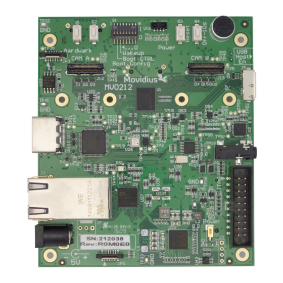
MV0182-R5. The design intent is that MV0212-R0 is funcnonally companble with MV0182-R5 with the eexcepnon of the inclusion of the larger 512MB memory in the MA2450 SoC. Figure 1: The MV0212 Development Board Intel Movidius Confdennal User Manual (MV0212-UM-1.2) -
Page 7: Mv0212 Board Specifcanon
Sensors BMI160 Inernal Measurement Unit. BMP_180 Pressure Sensor. Infrared Remote Control Sensor. Audio On board Microphone, Mono Audio input jack and Stereo Audio output jack. Table 1: Key Top Level Features Intel Movidius Confdennal User Manual (MV0212-UM-1.2) -
Page 8: Top-Level Block Diagram
Top-Level Blotk Diagram Figure 2: MV0212 System Blotk Diagram Intel Movidius Confdennal User Manual (MV0212-UM-1.2) -
Page 9: Pcb Overview
USB 3.0 Protessor Mitro B Audio Jatk HDMI Stereo + Port 3.3V JTAG Debug Gigabit Port Ethernet Port SD Card Power LED 5V DC Center PMI C Positve Ground Tabs Figure 3: PCB Top Overview Intel Movidius Confdennal User Manual (MV0212-UM-1.2) -
Page 10: Daughtercard Connecnons
Users must take care to ensure that daughtercards are only attached to the intended eexpansion port. There are no physical interlocks in the design to prevent incorrect daughtercard attachments. Intel Movidius Confdennal User Manual (MV0212-UM-1.2) -
Page 11: Movidius Pcb Revision System
The PCB silkscreen will contain the base revision for the PCB and supplemental labels are used thereafer to increase the MX or EX felds. Board Board Serial umber PCB Revision and Elettrital Revision Figure 5: Identfying PCB Revision and Serial umber (MV0212-R0) Intel Movidius Confdennal User Manual (MV0212-UM-1.2) -
Page 12: Getting Started Guide
5V Power tonnetton Olimex Dongle Figure 6: Illustraton of Required Parts Powering the Board Once the board has been mounted on the included tripod and the JTAG connected as shown in Figure 6, the Intel Movidius Confdennal User Manual (MV0212-UM-1.2) -
Page 13: Running Your Frst Applicanon
MDK_GettingStarted.pdf applicanon. 1 This assumes no user applicanon is booted. An applicanon booted from Flash can take control for D11, D12 and change the default on behaviour of the LEDS. Intel Movidius Confdennal User Manual (MV0212-UM-1.2) -
Page 14: Boot Confguraton And Switthes
Boot Confguraton and Switthes This secnon gives detailed informanon about the dip switch (8 channel) S1 and the four tacnle switches B1, B2, B3, B4. DIP Switth Connettvity Figure 9: Sthematt snippet showing DIP Switth Connettons Intel Movidius Confdennal User Manual (MV0212-UM-1.2) -
Page 15: Boot Confguranon Gpio Sharing
In limited cases it may be possible to use input pins if this possibility can be precluded. For the boot modes to be supported it is important that the state of the shared pin at reset is valid for the connected eexternal peripheral. Intel Movidius Confdennal User Manual (MV0212-UM-1.2) -
Page 16: Mv0212 Supported Boot Modes
Table 4: MV0212 Boot tonfguraton Optons 2 The DEBUG_HALT boot mode is mainly useful for troubleshoonng. It does not confgure the PLL, it just enables all clocks and then goes into an infnite loop. Intel Movidius Confdennal User Manual (MV0212-UM-1.2) -
Page 17: Default Dip Switch Selecnon
The factory default setng for the BOOT Selecnon DIP Switch is shown below. This setng selects Boot MODE 0exC which is SPIM 24 bit from the onboard 8 MB SPI Flash device. Figure 10: Default Boot Mode Confguraton Intel Movidius Confdennal User Manual (MV0212-UM-1.2) -
Page 18: Push Button Switch Funcnons
( ote: This button tannot turn O the system) Table 5: Push Button Spetiftaton User System Power Of Buttons Reset (Hold 10 set) Figure 11: Lotaton of the push button switthes Intel Movidius Confdennal User Manual (MV0212-UM-1.2) -
Page 19: System Clotks
To allow for maeximum feexibility and to account for the constrained availability of GPIOs on the MV0212 platorm an eexternal PLL peripheral is used. The device used is the CDCEL925 with a 27 MHz eexternal oscillator source. Figure 12: Blotk diagram of the CDCEL925 Clotk Generator Intel Movidius Confdennal User Manual (MV0212-UM-1.2) - Page 20 HDMI_PCLK_GEN Clock Source for HDMI-TX (ADV7513) PLL2 CAM_A_CLK_GEN Opnonal Clock source for Camera daughtercards on CAM_A interface PLL2 CAM_B_CLK_GEN Opnonal Clock source for Camera daughtercards on CAM_B interface Table 6: Clotk Generator Output Utlisaton Intel Movidius Confdennal User Manual (MV0212-UM-1.2)
-
Page 21: Auxiliary Gpio Usage
General purpose IO#2 for use by LCD/AP Connector LED1 LED1 (D11 on PCB) Dedicated PMIC LED1 control (Default on) LED2 LED2 (D12 on PCB) Dedicated PMIC LED2 control (Default on) Table 7: PMIC Auxiliary I/O Allotaton Intel Movidius Confdennal User Manual (MV0212-UM-1.2) - Page 22 LED2 LED1 5V_Present LED Figure 13: AUX LED Platement Intel Movidius Confdennal User Manual (MV0212-UM-1.2)
-
Page 23: Usb Subsystem
USB devices with the MV0212 as a host board. 6.2.1 USB Connettor limitatons The MV0212 motherboard provides a USB3.0 Type micro-B female connector at locanon J5. Unless the USB Intel Movidius Confdennal User Manual (MV0212-UM-1.2) -
Page 24: Usb Vbus Limitanons
The suggested mechanism to avoid this if it occurs is to use an eexternally powered USB hub in order to supply power to the eexternal USB rather than the MV0212 board itself. The hub can then be connected to the USB port J5 as normal. Intel Movidius Confdennal User Manual (MV0212-UM-1.2) -
Page 25: Lcd & Ap Expansion Port
AP/LCD interface. They are driven by the PMIC auexiliary I/O funcnon and control of these pins via sofware requires I2C communicanon from Myriad to the PMIC. As such they are most useful for funcnons such as stanc I/O confguranon. Table 8: LCD Expansion Port Feature Overview Intel Movidius Confdennal User Manual (MV0212-UM-1.2) -
Page 26: Lcd/Ap Eexpansion Port J10 Pinout
Reserved for Future Use VDD_5V VDD_5V 5V Power to Daughtercard, Maex 0.5A total FROM_MV0212 Table 9: LCD Expansion Port Pinout OTE: All digital logic signal levels are based on 1.8V I/O logic unless otherwise specifed. Intel Movidius Confdennal User Manual (MV0212-UM-1.2) -
Page 27: Camera Expansion Port
I2C communicanon from Myriad to the PMIC. As such they are most useful for funcnons such as control of stanc signals (e.g. reset) Table 10: Camera Expansion Port Feature Overview Intel Movidius Confdennal User Manual (MV0212-UM-1.2) -
Page 28: Camera A Eexpansion Port (J12) Pinout
WM8325_GPIO_10 Dedicated AuexiGPIO, I2C confg FROM_MV0212 RESERVED1 TP37 Reserved for future use RESERVED2 TP38 Reserved for future use VDD_5V VDD_5V 5V Power to D/c, Maex 0.5A total FROM_MV0212 Table 11: Camera Expansion Port Pinout Intel Movidius Confdennal User Manual (MV0212-UM-1.2) -
Page 29: Camera B Eexpansion Port (J13) Pinout
Dedicated Auexiliary GPIO, confgured via FROM_MV0212 RESERVED1 TP39 Reserved for future use RESERVED2 TP40 Reserved for future use VDD_5V VDD_5V 5V Power to D/c, Maex 0.5A total FROM_MV0212 Table 12: Camera Expansion Port Pinout Intel Movidius Confdennal User Manual (MV0212-UM-1.2) -
Page 30: Daughtertard Design Consideratons
Daughtercard with dual 2 lane MIPI cameras connected to the CAM_B Interface. Daughtercard which provides uplink to an Applicanons processor using a 4 lane MIPI confguranon Figure 15: MV0212 MIPI Connettons Example Some Important points to note: Intel Movidius Confdennal User Manual (MV0212-UM-1.2) -
Page 31: Common I/O Bus Descripnon
– – BOOT3 GPIO_OUT – Table 13: Common IO Funtton Sharing Breakdown Matng Connettor Destriptons The MV0212 is designed with a view to having daughtercards which are mounted using a direct PCB to PCB Intel Movidius Confdennal User Manual (MV0212-UM-1.2) -
Page 32: Connector Pin Numbering Convennon
To keep things easy for eexternal daughtercard designers, the ofcial pinout (as described in the Samtec datasheet) is used for all daughtercard layouts. As such only the Movidius MV0212 motherboard uses this non-standard footprint. To ensure companbility daughtercard designers should only need to apply the following two steps: 1. - Page 33 Figure 16: Example Samtet Footprint Retommendaton Intel Movidius Confdennal User Manual (MV0212-UM-1.2)
-
Page 34: Daughtercard Mechanical Specifcanon
This secnon provides mechanical details of the PCB hole placement and connector posinons. This mechanical specifcanon is fully backwards companble with MV0182. Please see secnon for details of other aspects of the mechanical specifcanon. Figure 17: MV0212 Board Methanital Spetiftaton Intel Movidius Confdennal User Manual (MV0212-UM-1.2) - Page 35 SPI rather than I2C. This is not correct as there are no SPI connecnons to this IC. Limitaton No funcnonal limitanon. This is purely a cosmenc issue. Soluton This teext will be removed in the event of any subsequent respin of this board. Intel Movidius Confdennal User Manual (MV0212-UM-1.2)
- Page 36 PDF Version of the released schemancs. OTE: (NM) variant is the schemanc showing which subset of components which are mounted. MV0212_R0M0E0_Release\Pmic_eeprom Contents of the Power management IC EEPROM (U43) confguranon in Intel Heex format. Table 16: Referente Dotumentaton Intel Movidius Confdennal User Manual (MV0212-UM-1.2)
Need help?
Do you have a question about the Movidius MV0212 and is the answer not in the manual?
Questions and answers