Table of Contents
Advertisement
Quick Links
Advertisement
Chapters
Table of Contents

Related Manuals for Intel MB896


Summary of Contents for Intel MB896
- Page 1 MB896 Intel Pentium ® Mini-ITX Motherboard USER’S MANUAL Version 1.0...
- Page 2 Award is a registered trademark of Award Software International, Inc. PS/2 is a trademark of International Business Machines Corporation. Intel and Pentium M are registered trademarks of Intel Corporation. Microsoft Windows is a registered trademark of Microsoft Corporation. Winbond is a registered trademark of Winbond Electronics Corporation.
-
Page 3: Table Of Contents
Setting the Jumpers ............9 Connectors on MB896.............12 BIOS Setup ............24 Drivers Installation ........49 Intel Chipset Software Installation Utility ......50 VGA Drivers Installation..........52 AC97 Codec Audio Driver Installation......54 LAN Drivers Installation ..........55 Appendix ............57 A. I/O Port Address Map..........57 B. - Page 4 IMPORTANT NOTE: When the system boots without the CRT being connected, there will be no image on screen when you insert the CRT/VGA cable. To show the image on screen, the hotkey must be pressed. THE MB896 MINI ITX MOTHERBOARD MB896 User’ s Manual...
-
Page 5: Introduction
Accelerator 900 (Intel® GMA 900) architecture, operates at core speeds of up to 320 MHz. It features a low-power design, is validated with the Intel® Pentium® M and Intel® Celeron® M processors on 90nm process. With one DIMM socket on board, the board supports up to 1GB of DDR2 533 MHz system memory. -
Page 6: Checklist
INTRODUCTION Checklist Your MB896 package should include the items listed below. • The MB896 Pentium ® M Mini-ITX motherboard • This User’s Manual • 1 CD containing chipset drivers and flash memory utility • Cable kit (IDE, Serial port, Serial ATA) -
Page 7: Mb896 Specifications
INTRODUCTION MB896 Specifications Form Factor Mini ITX CPU Type Intel Pentium M / Celeron M (Dothan Core only) CPU Voltage 0.700V ~ 1.708V System Speed Up to 2.26GHz CPU FSB 533 /400MHz FSB L2 Cache 2MB (Pentium M) / 512KB (Celeron M) CPU integrated Green /APM APM1.2... - Page 8 INTRODUCTION MB896 User’ s Manual...
-
Page 9: Board Dimensions
INTRODUCTION Board Dimensions MB896 User’ s Manual... -
Page 10: Installations
INSTALLATIONS Installations This section provides information on how to use the jumpers and connectors on the MB896 in order to set up a workable system. The topics covered are: Installing the CPU............. 7 Installing the Memory............8 Setting the Jumpers............9 Connectors on MB896 ............ -
Page 11: Installing The Cpu
INSTALLATIONS Installing the CPU ® The MB896 board supports a Socket 479 processor socket for Intel ® ® Pentium M or Celeron M processors. The processor socket comes with a screw to secure the processor. As shown in the left picture below, loosen the screw first before inserting the processor. -
Page 12: Installing The Memory
INSTALLATIONS Installing the Memory The MB896 board supports one DDR2 memory socket for a maximum total memory of 1GB in DDR2 memory type. Installing and Removing Memory Modules To install the DDR2 modules, locate the memory slot on the board and perform the following steps: 1. -
Page 13: Setting The Jumpers
INSTALLATIONS Setting the Jumpers Jumpers are used on MB896 to select various settings and features according to your needs and applications. Contact your supplier if you have doubts about the best configuration for your needs. The following lists the connectors on MB896 and their respective functions. - Page 14 INSTALLATIONS Jumper Locations on MB896 Jumpers on MB896 ................Page JP2: Pentium M Vcc Voltage Selection ..........11 JP3: LCD Panel Power Selection.............11 JP4: Clear CMOS Setting..............11 JP5: CompactFlash Slave/Master Selection........11 JP6: 1394 EPROM Write Selection..........11 IMPORTANT NOTE: When the system boots without the CRT being connected, there will be no image on screen when you insert the CRT/VGA cable.
- Page 15 JP3: LCD Panel Power Selection LCD Panel Power 3.3V JP4: Clear CMOS Setting Setting Normal Clear CMOS JP5: CompactFlash Slave/Master Selection CF Setting Master Slave JP6: 1394 EPROM Write Selection 1394 EPROM For EPROM Write Normal MB896 User’ s Manual...
-
Page 16: Connectors On Mb896
INSTALLATIONS Connectors on MB896 The connectors on MB896 allows you to connect external devices such as keyboard, floppy disk drives, hard disk drives, printers, etc. The following table lists the connectors on MB896 and their respective functions. Connector Locations on MB896............13 Connector Locations on MB896............13... -
Page 17: Connector Locations On Mb896
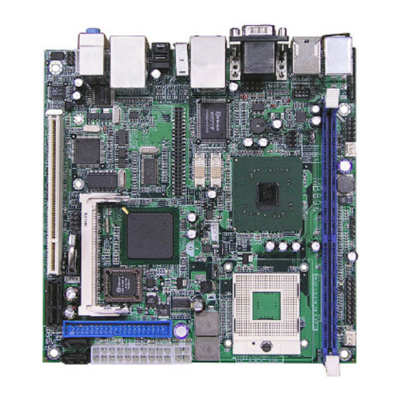
INSTALLATIONS Connector Locations on MB896 MB896 User’ s Manual... -
Page 18: Cn1: Ps/2 Keyboard And Ps/2 Mouse Connectors
N.C. CN2: COM1 and VGA Connector Signal Name Pin # Pin # Signal Name Not Used [ [ [ [ Signal Name Pin # Pin # Signal Name Green Blue N.C. N.C. N.C. N.C. HSYNC VSYNC MB896 User’ s Manual... -
Page 19: J4: S-Video And Rca Connectors
Pin # Signal Name Ground +12V Rotation detection FAN2: CPU Fan Power Connector FAN2 is a 3-pin header for the CPU fan. The fan must be a 12V fan. Pin # Signal Name Ground +12V Rotation detection MB896 User’ s Manual... -
Page 20: Ide1: Ide Connector
FDD1: Floppy Drive Connector FDD1is a slim 26-pin connector and will support up to 2.88MB FDD. Signal Name Pin # Pin # Signal Name INDEX DRV_SEL DSK_CH MOTOR DINST STEP WDATA WGATE TRACK WPROT RDATA SIDE MB896 User’ s Manual... -
Page 21: J11: Atx_12V Connector
Pin # Signal Name 3.3V 3.3V -12V 3.3V Ground Ground PS-ON Ground Ground Ground Ground Ground Power good 5VSB +12V +12V Ground +3.3V J1: IrDA Connector Pin # Signal Name No connect Ir RX Ground Ir TX MB896 User’ s Manual... -
Page 22: J2: Digital I/O
This connector provides an interface to a speaker for audio tone generation. An 8-ohm speaker is recommended. Pin # Signal Name Speaker out No connect Ground Power LED: Pins 11 - 15 Pin # Signal Name Power LED No connect Ground No connect Ground MB896 User’ s Manual... -
Page 23: J6: Usb5/6 Port Pin Header
This connector connects to the hard drive activity LED on control panel. This LED will flash when the HDD is being accessed. Pin # Signal Name HDD Active J6: USB5/6 Port Pin Header Signal Name Signal Name Ground Ground MB896 User’ s Manual... -
Page 24: J7: Com2 Serial Port
TX0- TX0+ Ground Ground TX1- TX1+ 5V/3.3V Ground TX3- TX3+ TX2- TX2+ Ground Ground TXC- TXC+ 5V/3.3V ENABKL +12V +12V J9: LCD Backlight Setting Pin # Signal Name +12V Backlight Enable Ground J14: Mini PCI Connector MB896 User’ s Manual... -
Page 25: J15: Speaker Connector
Rear Audio R Rear Audio L Front Audio R Front Audio L Mic In VREF Out Ground REMARKS: To use the front audio connector, the jumpers on pin 1-3 and pin 2-4 must be removed. J19: PCI-E(x1) Slot MB896 User’ s Manual... -
Page 26: J20: Cd-In Pin Header
SDVOC_Green- SDVOC_Red+ SDVOC_Red- SDVO TVClkIn+ SDVO TVClkIn- SDVOB Int+ SDVOB Int- SDVO CtrlData SDVO CtrlClk SDVOB Clk+ SDVOB Clk- SDVOB Blue+ SDVOB Blue- SDVOB Green+ SDVOB Green- BA21 SDVOB Red+ SDVOB Red- SDVO Stall+ SDVO Stall- MB896 User’ s Manual... - Page 27 INSTALLATIONS This page is intentionally left blank. MB896 User’ s Manual...
-
Page 28: Bios Setup
Standard CMOS Setup..............27 Advanced BIOS Features..............30 Advanced Chipset Features...............33 Integrated Peripherals................36 Power Management Setup..............40 PNP/PCI Configurations..............43 PC Health Status................45 Frequency/Voltage Control..............46 Load Fail-Safe Defaults..............47 Load Optimized Defaults..............47 Set Supervisor/User Password ............47 Save & Exit Setup................47 Exit Without Saving................47 MB896 User’ s Manual... -
Page 29: Bios Introduction
BIOS Introduction The Award BIOS (Basic Input/Output System) installed in your computer system’s ROM supports Intel p rocessors. The BIOS provides critical low-level support for a standard device such as disk drives, serial ports and parallel ports. It also adds virus and password protection as well as special support for detailed fine-tuning of the chipset controlling the entire system. - Page 30 These defaults have been carefully chosen by both Award and your system manufacturer to provide the absolute maximum performance and reliability. Changing the defaults could cause the system to become unstable and crash in some cases. MB896 User’ s Manual...
-
Page 31: Standard Cmos Setup
The following describes each item of this menu. Date The date format is: Day : Sun to Sat Month : 1 to 12 Date : 1 to 31 Year : 1999 to 2099 MB896 User’ s Manual... - Page 32 These fields identify the types of floppy disk drive A or drive B that has been installed in the computer. The available specifications are: 360KB 1.2MB 720KB 1.44MB 2.88MB 5.25 in. 5.25 in. 3.5 in. 3.5 in. 3.5 in. MB896 User’ s Manual...
- Page 33 The system boot will not be halted for a disk error; it will stop for all other errors. All, But Disk/Key The system boot will not be halted for a key- board or disk error; it will stop for all others. MB896 User’ s Manual...
-
Page 34: Advanced Bios Features
When the CPU requests data, the system transfers the requested data from the main DRAM into cache memory, for even faster access by the CPU. These items allow you to enable (speed up memory access) or disable the cache function. By default, these items are Enabled. MB896 User’ s Manual... - Page 35 When enabled, you can set the two typematic controls listed next. By default, this field is set to Disabled. Typematic Rate (Chars/Sec) When the typematic rate is enabled, the system registers repeated keystrokes speeds. Settings are from 6 to 30 characters per second. MB896 User’ s Manual...
- Page 36 Disabled, the BIOS will not report the missing floppy drive to Win95/98. Small Logo (EPA) Show The EPA logo appears at the right side of the monitor screen when the system is boot up. The default setting is Enabled. MB896 User’ s Manual...
-
Page 37: Advanced Chipset Features
This option allows you to insert a delay between the RAS (Row Address Strobe) and CAS (Column Address Strobe) signals. This delay occurs when the SDRAM is written to, read from or refreshed. Reducing the delay improves the performance of the SDRAM. MB896 User’ s Manual... - Page 38 PEG/On Chip VGA Control: Auto On-Chip Frame Buffer Size: 8MB DVMT Mode: DVTM DVMT/Fixed Memory Size: 128MB Boot Display: Auto Panel Scaling: Auto Panel Number: 1024x768 18 bit SC TV Standard: Off Video Connector: Automatic TV Format: Auto MB896 User’ s Manual...
- Page 39 18bit SC 1400x1050 18bit DC 1600x1200 18bit DC Onboard PCI-E LAN By default, this setting is enabled. LAN PXE Option ROM By default, this setting is disabled. Other selections include ICH6 Integrated LAN and Marvell PCI-E LAN. MB896 User’ s Manual...
-
Page 40: Integrated Peripherals
PATA IDE Mode Secondary SATA port P0, P2 is Primary Phoenix - AwardBIOS CMOS Setup Utility Onboard Device Enabled ITEM HELP USB Controller Enabled Menu Level > USB 2.0 Controller Disabled USB Keyboard Support AC97 Audio Select Auto MB896 User’ s Manual... - Page 41 When Auto is selected, the BIOS will select the best available mode. IDE Primary/Secondary Master/Slave UDMA These fields allow your system to improve disk I/O throughput to 33Mb/sec with the Ultra DMA/33 feature. The options are Auto and Disabled. MB896 User’ s Manual...
- Page 42 If you install an add-in FDC or the system has no floppy drive, select Disabled in this field. This option allows you to select the onboard FDD port. MB896 User’ s Manual...
- Page 43 This field determines the UART 2 mode in your computer. The default value is Normal. Other options include IrDA and ASKIR. PWRON After PWR-Fail This field sets the system power status whether on or off when power returns to the system from a power failure situation. MB896 User’ s Manual...
-
Page 44: Power Management Setup
Min. Power Saving Minimum power management Max. Power Saving Maximum power management. User Define Each of the ranges is from 1 min. to 1hr. Except for HDD Power Down which ranges from 1 min. to 15 min. MB896 User’ s Manual... - Page 45 Wake up by PCI Card By default, this field is disabled. Power On by Ring This field enables or disables the power on of the system through the modem connected to the serial port or LAN. MB896 User’ s Manual...
- Page 46 When an I/O device wants to gain the attention of the operating system, it signals this by causing an IRQ to occur. When the operating system is ready to respond to the request, it interrupts itself and performs the service. MB896 User’ s Manual...
-
Page 47: Pnp/Pci Configurations
MPEG ISA/VESA VGA card. When this field is disabled, a PCI/VGA cannot work with an MPEG ISA/VESA card. Maximum Payload Size The default setting of the PCI Express Maximum Payload Size is 4096. MB896 User’ s Manual... - Page 48 BIOS SETUP MB896 User’ s Manual...
-
Page 49: Pc Health Status
This field enables or disables the smart fan feature. At a certain temperature, the fan starts turning. Once the temperature drops to a certain level, it stops turning again. Smart Fan Tolerance Value The default value is 5. MB896 User’ s Manual... -
Page 50: Frequency/Voltage Control
This field enables or disables the auto detection of the PCI clock. Spread Spectrum Modulated This field sets the value of the spread spectrum. The default setting is Disabled. This field is for CE testing use only MB896 User’ s Manual... -
Page 51: Load Fail-Safe Defaults
Select this option to exit the Setup utility without saving the changes you have made in this session. Typing “Y” will quit the Setup utility without saving the modifications. Typing “N” will return you to Setup utility. MB896 User’ s Manual... - Page 52 BIOS SETUP This page is intentionally left blank. MB896 User’ s Manual...
-
Page 53: Drivers Installation
AC97 Codec Audio Driver Installation......54 LAN Drivers Installation ..........55 IMPORTANT NOTE: After installing your Windows operating system (Windows 2000/ XP), you must install first the Intel Chipset Software Installation Utility before proceeding with the drivers installation. MB896 User’ s Manual... -
Page 54: Intel Chipset Software Installation Utility
Plug & Play INF support for Intel chipset components. Follow the instructions below to complete the installation under Windows 2000/XP. 1. Insert the CD that comes with the board. Click Intel Chipsets and then Intel(R) 915GMChipset Drivers. 2. Click Intel(R) Chipset Software Installation Utility. - Page 55 6. The Setup process is now complete. Click Finish to restart the computer and for changes to take effect. When the computer has restarted, the system will be able to find some devices. Restart your computer when prompted. MB896 User’ s Manual...
-
Page 56: Vga Drivers Installation
VGA Drivers Installation To install the VGA drivers, follow the steps below to proceed with the installation. 1. Insert the CD that comes with the motherboard. Click Intel Chipsets and then Intel(R) 915GMChipset Drivers. 2. Click Intel(R) 915GMChipset Family Graphics Driver. - Page 57 When you have restarted the computer, your computer screen will be blank. At this point, press CTRL-ALT-F1 simultaneously, if you are using CRT monitor. If you are using LVDS LCD panel, press CTRL-ALT-F3. If you are using DVI monitor, press CTRL-ALT-F4. MB896 User’ s Manual...
-
Page 58: Ac97 Codec Audio Driver Installation
AC97 Codec Audio Driver Installation Follow the steps below to install the Realtek AC97 Codec Audio Drivers. 1. Insert the CD that comes with the motherboard. Click Intel Chipsets and then Intel(R) 915GMChipset Drivers. 2. Click Realtek AC'97 Codec Audio Driver. -
Page 59: Lan Drivers Installation
DRIVERS INSTALLATION LAN Drivers Installation Follow the steps below to complete the installation of the Intel PRO LAN drivers. 1. Insert the CD that comes with the motherboard. Click LAN Card and then Intel(R) PRO LAN Drivers. 2. Click Install Base Software to continue. - Page 60 3. Click Next to agree with the license agreement. 4. Click Next when the Readme Information screen appears to proceed with the drives installation process. 5. When the Installation is complete, click Finish for the changes to take effect. MB896 User’ s Manual...
-
Page 61: Appendix
Parallel Port #1(LPT1) 360 - 36F Network Ports 3B0 - 3BF Monochrome & Printer adapter 3C0 - 3CF EGA adapter 3D0 - 3DF CGA adapter 3F0h - 3F7h Floppy Disk Controller 3F8h - 3FFh Serial Port #1(COM1) MB896 User’ s Manual... -
Page 62: Interrupt Request Lines (Irq)
Serial Port #2 IRQ4 Serial Port #1 IRQ5 Reserved IRQ6 Floppy Disk Controller IRQ7 Parallel Port #1 IRQ8 Real Time Clock IRQ9 Reserved IRQ10 Reserved IRQ11 Reserved IRQ12 PS/2 Mouse IRQ13 80287 IRQ14 Primary IDE IRQ15 Secondary IDE MB896 User’ s Manual... -
Page 63: Watchdog Timer Configuration
Parameter incorrect!!\n"); return 1; if (Init_W627EHF() == 0) printf(" Winbond 83627HF is not detected, program abort.\n"); return 1; bTime = strtol (argv[1], endptr, 10); printf("System will reset after %d seconds\n", bTime); EnableWDT(bTime); return 0; //=========================================================================== MB896 User’ s Manual... - Page 64 #include <dos.h> //=========================================================================== unsigned int W627EHF_BASE; void Unlock_W627EHF (void); void Lock_W627EHF (void); //=========================================================================== unsigned int Init_W627EHF(void) unsigned int result; unsigned char ucDid; W627EHF_BASE = 0x2E; result = W627EHF_BASE; ucDid = Get_W627EHF_Reg(0x20); if (ucDid == 0x88) goto Init_Finish; MB896 User’ s Manual...
- Page 65 APPENDIX W627EHF_BASE = 0x4E; result = W627EHF_BASE; MB896 User’ s Manual...
- Page 66 // THIS CODE AND INFORMATION IS PROVIDED "AS IS" WITHOUT WARRANTY OF ANY // KIND, EITHER EXPRESSED OR IMPLIED, INCLUDING BUT NOT LIMITED TO THE // IMPLIED WARRANTIES OF MERCHANTABILITY AND/OR FITNESS FOR A PARTICULAR // PURPOSE. //=========================================================================== #ifndef __W627EHF_H #define __W627EHF_H //=========================================================================== #define W627EHF_INDEX_PORT (W627EHF_BASE) MB896 User’ s Manual...
- Page 67 APPENDIX #define W627EHF_DATA_PORT (W627EHF_BASE+1) //=========================================================================== #define W627EHF_REG_LD 0x07 //=========================================================================== MB896 User’ s Manual...
- Page 68 APPENDIX #define W627EHF_UNLOCK 0x87 #define W627EHF_LOCK 0xAA //=========================================================================== unsigned int Init_W627EHF(void); void Set_W627EHF_LD( unsigned char); void Set_W627EHF_Reg( unsigned char, unsigned char); unsigned char Get_W627EHF_Reg( unsigned char); //=========================================================================== #endif //__W627EHF_H MB896 User’ s Manual...
Need help?
Do you have a question about the MB896 and is the answer not in the manual?
Questions and answers