Intel G41 Express Chipset User Manual
Intel g41 express chipset & intel ich7 chipset based m/b for lga 775 quad core ready intel core processor family
Hide thumbs
Also See for G41 Express Chipset:
- User manual (20 pages) ,
- Simplified user manual (7 pages) ,
- Thermal/mechanical design manuallines (44 pages)
Table of Contents
Advertisement
USER'S MANUAL
Of
Intel G41 Express Chipset
&
Intel ICH7 Chipset
Based
M/B for LGA 775 Quad Core Ready
Intel Core Processor Family
No. G03-MI5G41SVMD3F
Rev: 10
,
Release date: May
2010
Trademark:
* Specifications and Information contained in this documentation are furnished for information use only, and are
subject to change at any time without notice, and should not be construed as a commitment by manufacturer.
Advertisement
Table of Contents

Related Manuals for Intel G41 Express Chipset


Summary of Contents for Intel G41 Express Chipset
- Page 1 USER'S MANUAL Intel G41 Express Chipset & Intel ICH7 Chipset Based M/B for LGA 775 Quad Core Ready Intel Core Processor Family No. G03-MI5G41SVMD3F Rev: 10 , Release date: May 2010 Trademark: * Specifications and Information contained in this documentation are furnished for information use only, and are...
- Page 2 Environmental Safety Instruction Avoid the dusty, humidity and temperature extremes. Do not place the product in any area where it may become wet. 0 to 40 centigrade is the suitable temperature. (The figure comes from the request of the main chipset) Generally speaking, dramatic changes in temperature may lead to contact malfunction and crackles due to constant thermal expansion and contraction from the welding spots’...
-
Page 3: Table Of Contents
TABLE OF CONTENT CHAPTER 1 INTRODUCTION OF INTEL G41 MOTHERBOARD SERIES FEATURES OF MOTHERBOARD ................1 1-1.1 SPECIAL FEATURES OF MOTHERBOARD ..........2 SPECIFICATION ......................3 ITEM CHECKLIST....................... 3 LAYOUT DIAGRAM....................4 CHAPTER 2 HARDWARE INSTALLATION INSTALL LGA 775 SUPPORTED INTEL PROCESSOR........... 5 INSTALL MEMORY .................... -
Page 4: Chapter 1 Introduction Of Intel G41 Motherboard Series
Chapter 1 Introduction of Intel G41 Motherboard Series 1-1 Features of motherboard The Intel G41 chipset motherboard series are based on the latest Intel G41 Express Chipset and Intel ICH7 Chipset technology which supports the innovative 65nm and ® ®... -
Page 5: 1-1.1 Special Features Of Motherboard
computing. But if you insist to gain more system performance with variety possibilities of the components you choose, please be careful and make sure to read the detailed descriptions of these value added product features, please get them in the coming section. -
Page 6: Specification
1-2 Specification Spec Description Design Micro ATX form factor; PCB size: 22.5*17.1cm Chipset Intel G41 Memory Controller Hub (MCH) Chipset Intel 82801GB I/O Controller Hub (ICH7) Chipset ® ® ® Supports the innovative 65nm and 90nm Intel Celeron 400, Intel ®... -
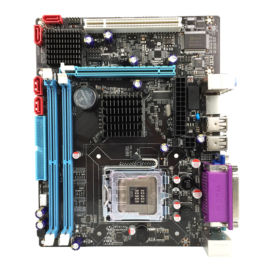
Page 7: Layout Diagram
CPU FAN SYSFAN1 USB Ports USB Power ON Jumper (JP2) RJ-45 Over USB Ports 6-CH Audio Connector IDE Connector Intel G41Express Megabit LAN Chip Chipset PCI Express x16 Slot Intel 82801GB ICH Chipset 32-bit PCI Slot HDMI-SPDIF Header ALC662 USB Header... -
Page 8: Chapter 2 Hardware Installation
Install LGA 775 Supported Intel Processor This motherboard provides a 775-pin surface mount, LGA775 Land Grid Array socket, referred to as the LGA775 socket supports Intel Pentium Dual Core processor in the 775 Pin package utilizes Flip-Chip Land Grid Array (FC-LGA) package technology. -
Page 9: Expansion Cards
Recommend DIMM Module Combination One DIMM Module ----Plug in DIMM1 Two DIMM Modules---Plug in DIMM1 and DIMM2 for Dual channel function For Dual channel Limited! Dual channel function only supports when 2 DIMM Modules plug in either both DIMM1 & DIMM2 DIMM1 &... -
Page 10: Connectors
PE1 / PCI-E x16 Slot 32-bit PCI Slot Chapter 3 Connectors, Headers & Jumpers Setting 3-1 Connectors Power Connector (24-pin block): ATXPWR ATX Power Supply connector: This is a new defined 24-pins ROW1 ROW2 connector that usually comes ROW1 ROW2 ROW1 ROW2 3.3V 3.3V... - Page 11 20-pin power plug 24-pin power plug (2) ATX 12V Power Connector (4-pin block) : ATX12V This is a new defined 4-pin connector that usually comes with ATX Power Supply. The ATX Power Supply which fully supports AM2 processor must including this connector for support extra 12V voltage to maintain system power consumption.
-
Page 12: Headers
Two hard disks can be connected to each connector. The first HDD is referred to as the “Master” and the second HDD is referred to as the “Slave”. For performance issues, we strongly suggest you don’t install a CD-ROM or DVD-ROM drive on the same IDE channel as a hard disk. - Page 13 (2) USB Port Headers (9-pin) : USB2 This USB header is used for connecting the additional USB port plug. By attaching an option USB cable, your can be provided with two additional USB plugs affixed to the back panel. USB2 Pin 1 USB Port Header (3) Speaker connector: SPEAK...
-
Page 14: Jupper Setting
positive, while the black should be ground. Connect the fan’s plug to the board taking into consideration the polarity of connector. +12V CPUFAN CPUFAN IN CPUFAN OUT SYSFAN1 (11) SPDIF Out header: SPDIF Out The SPDIF output is capable of providing digital audio to external speakers or compressed AC3 data to an external Dolby digital decoder. -
Page 15: Usb Power-On Enabled/Disabled
USB Power-on Enabled/Disabled: JP2 1-2 Closed: USB Power On Disable (Default) 2-3 Closed: USB Power On Enabled USB Power On Setting (3) CMOS RAM Clear (2-pin): JBAT A battery must be used to retain the motherboard configuration in CMOS RAM short 1-2 pins of JBAT to clear the CMOS data. -
Page 16: Chapter 4 Useful Help
Chapter 4 Useful Help 4-1 How to Update BIOS Step 1. Prepare a bootable disc. (You may make one by click START click RUN type SYS A: click OK) Step 2. Download upgrade tools and the latest BIOS files of the motherboard from official website and then make a copy of it to your bootable disk after decompressing these files Step 3.