
Related Manuals for Federal VHSS Series


Summary of Contents for Federal VHSS Series
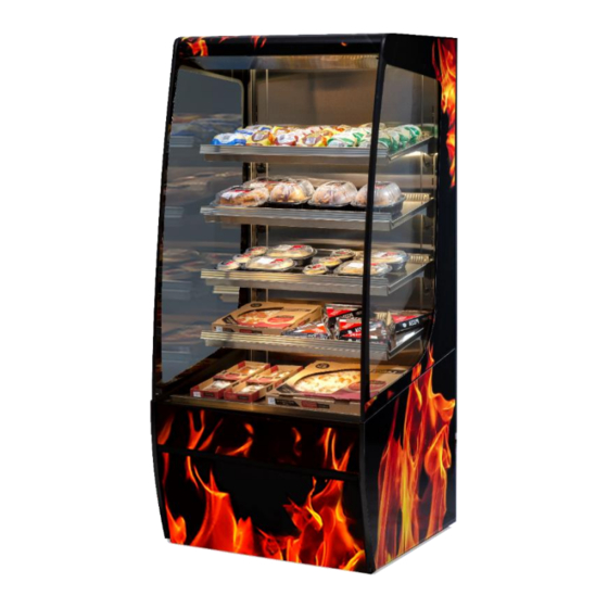
- Page 1 E3981 Rev B 12/21/21 INSTALLATION & OPERATIONS INSTRUCTIONS VHSS: Heated Models Engineering and technical data are subject to change without notice. FEDERAL INDUSTRIES 215 Federal Ave Belleville, WI 53508...
-
Page 2: Table Of Contents
CONTENTS Introduction ................................3 1.1 Serial Number ..............................3 Warning Labels & Safety Instructions ........................4 PRIOR TO UNPACKING EQUIPMENT! ......................... 5 General Electrical & Grounding ..........................6 4.1 Cord Connected ..............................6 Installation Instructions ............................7 5.1 Locating The Display Case..........................7 5.2 Removing Case From Shipping Skid ......................... -
Page 3: Introduction
(1) Introduction Thank you for purchasing a Federal Industries display case. This manual contains important instructions for installing and servicing your new display case. A repair parts list and wiring diagram are also included in the manual. Read all of these documents carefully before installing or servicing your case. -
Page 4: Warning Labels & Safety Instructions
NOTICE: message, you may damage your case. The warning and safety labels shown throughout this manual are placed on your Federal Industries case at the factory. Follow all warning label instructions. If any warning or safety labels become lost or damaged, call our customer service department at (800) 356-4206 for replacements. -
Page 5: Prior To Unpacking Equipment
PRIOR TO UNPACKING EQUIPMENT! Inspect for shipping damage. You are responsible for filing all freight claims with the delivering truck line. Inspect all cartons and crates for damage as soon as they arrive. If damage is noted to shipping crates, cartons, or if a shortage is found, note this on the bill of lading (all copies) prior to signing. -
Page 6: General Electrical & Grounding
(4) GENERAL ELECTRICAL & GROUNDING WARNING: Improper or faulty hookup of electrical components in the display case can result in severe injury or death. 4.1 CORD CONNECTED All standard models are supplied with a power cord that is properly sized to the amperage requirements of the case. -
Page 7: Installation Instructions
(5) INSTALLATION INSTRUCTIONS 5.1 LOCATING THE DISPLAY CASE The case(s) should be located where it is not subjected to the direct rays of the sun, heating ducts, grills, radiator, or ceiling fans, nor should it be located near open doors or main door entrances. -
Page 8: Single Case Installation (Stand Alone Units)
REMOVE CASE OFF OF FRONT OR BACK OF SKID ONLY PULL SKID AWAY FROM CASE AND GENTLY SET CASE ON FLOOR 5.2.1 Removing Packaging Material Remove bubble wrap and packing material for all shelves and panel, brackets, etc. If it is necessary to remove tape residue from plastic materials, use cleaning compounds recommended in the cleaning section of this manual. - Page 9 LEVEL CASE USING THESE SURFACES Adjust the (4) outside leg levelers as needed to level the case in each direction. NOTE: If necessary, use a wood or plastic shim under each leg leveler to avoid scratching the tile floor. Sealing Unit to The Floor After the unit is positioned and the leg levelers are turned out, the unit needs to be sealed to the floor for NSF approved installation.
-
Page 10: Joining Kit Installation (Vhss To Vhss)
(6) JOINING KIT INSTALLATION (VHSS TO VHSS) 6.1 INSTALLATION FOR JOINED CASES (LINEUPS) 6.1.1 Join heated to heated (VHSS to VHSS) Remove all Shelves, display deck, interior back panel(s), exterior back(s), front and rear base panel, and ceiling. Position the right or left most unit in the desired position for the lineup to start, and level this case. - Page 11 JOINING TRIM Replace all panels that were previously removed. 6.1.2 Join units with glass divider, or join heated to non-refrigerated For this joining configuration, one unit will come with a lower end panel preinstalled with glass. Five bolt holes will be exposed on the outside of this panel and are the locations that will be used to join the units together.
- Page 12 TOP JOIN TRIM REAR JOIN TRIM DETAIL A 7. Finish the joining process loosening the glass trim on the case to slide the joining trim over the existing trim and secure with the existing fasteners. Do this for both the top trim and the rear trim.
-
Page 13: Feature Overview
(7) FEATURE OVERVIEW TOP GLASS TRIM SHELF 4 (TOP) GLASS TRIM EXTRUSION REAR GLASS TRIM SHELF 1 (BTM) END GLASS DISPLAY DECK FRONT PANEL FLIP-DOWN END PANEL CONTROL PANEL CONTROL DOOR ASSEMBLY PRICE TAG MOLDING SHELF BRACKET HEATER CORD HEATER RECEPTACLE POWER SWITCH DOOR MAGNET SHELF HEATER CONTROLS... -
Page 14: Shelving Installation And Removal
(8) SHELVING INSTALLATION AND REMOVAL 8.1 SHELF BRACKETS AND SUPPORTS Follow the instructions shown in the diagram below to install shelf brackets. Follow the “LEVEL” path if you want shelves to have no tilt or follow the “SLANTED” path if you want shelves with tilt. Ensure brackets are well seated and face the proper direction. - Page 15 Make the heater connections from the back of the shelf into the receptacle of the vertical frame of the unit. Remove the receptacle cap and push the heater cord (the heater cord comes out of the left side of the shelf) into the nearest heater receptacle. The cord will only insert in one direction as shown below.
- Page 16 To remove the deck simply lift on the front handle and rotate the front of the deck upward. Hold the assembly in place and use your other hand to disengage the heater cord from the tub. Then simply lift the deck from the unit. Installation is the reverse of removal. E3981 VHSS...
-
Page 17: Control Operation
(9) CONTROL OPERATION NOTICE Load items at 170°F or warmer. At time of loading, items stocked in unit MUST be pre- heated at 170°F or warmer. The controls are found behind the front panel pictured below. Pull forward on the short handle of the flip down panel and gently rotate the panel down and let it rest on the toe kick. - Page 18 Use the following procedure to adjust the control setpoints. The temperature controllers each reference one temperature probe that is mounted in the deck or shelf depending on the control. Do not locate the probe to a different position. Shelf temperature settings are digitally controlled via factory settings 1-9. Setting “1” provides the coolest surface temperatures while setting “9”...
-
Page 19: Food Packaging Recommendations
(10) FOOD PACKAGING RECOMMENDATIONS This merchandiser is designed to be used with pre-packaged product only. All food items placed in the merchandiser must be packaged. No foods should be placed in the merchandiser without packaging. NOTICE Load items at 170°F or warmer. At time of loading, items stocked in unit MUST be pre- heated at 170°F or warmer. -
Page 20: Cleaning Instructions
(11) CLEANING INSTRUCTIONS 11.1 DAILY CLEANING The case should be cleaned thoroughly, as described in the weekly cleaning section before it is used for the first time. NOTICE: Avoid splashing or soaking any electrical components with water to prevent electrical damage to the case. NOTICE: Shut off power switch and remove all product from case. - Page 21 NOTICE: Shut off power switches and remove all product from case. Allow enough time for the unit to reach room temperature before proceeding with cleaning. NOTICE: Remove all product from case before proceeding with cleaning procedure. NOTICE: This case is not designed to be cleaned by flushing. 1.
-
Page 22: Service
For warranty service requests and all technical support, including compressors and other service parts please contact: Phone: (833) 238-8168 Email: techservice@partstown.com Federal Industries has partnered with Parts Town for ALL Non-Warranty Part Identification, Pricing, Lead Times, Orders & Freight Quotes. Please contact Parts Town directly if you need parts: Website: PartsTown.com Email: CustomerService@PartsTown.com... -
Page 23: Sale & Disposal
SALE & DISPOSAL 13.1 OWNER RESPONSIBILITY If you sell or give away your Federal Industries case you must make sure that all safety labels and the Installation-Service Manual are included with it. If you need replacement labels or manuals, Federal Industries will provide them free of charge. Contact the customer service department at Federal Industries at (800) 356-4206. -
Page 24: Troubleshooting
(14) TROUBLESHOOTING Pre-Service Checklist You may avoid the cost and inconvenience of an unnecessary service call by first reviewing this checklist of frequently encountered situations that can cause unsatisfactory case performance. Case Does Not Operate Check for disconnected power supply. Check for tripped breaker on blown fuse. -
Page 25: Wiring Diagrams
(15) WIRING DIAGRAMS E3981 VHSS... -
Page 26: Vhss Service Parts
(16) VHSS SERVICE PARTS Heated Shelves and Deck LEFT SHELF RIGHT SHELF CAUTION Model Shelf Part# Deck Part# BRACKET BRACKET HOT STICKER VHSS2460 SA6035-S SA6041-S 67-21204-L 67-21204-R 91-10207 VHSS3660 SA6035-1S SA6041-1S 67-21204-L 67-21204-R 91-10207 VHSS4860 SA6035-2S SA6041-2S 67-21204-L 67-21204-R 91-10207 VHSS2478 SA6035-S SA6041-S 67-21204-L 67-21204-R 91-10207... -
Page 27: Options
(17) OPTIONS 17.1 REAR SWINGING DOOR 828/829-9640-INTB BLACK INTERIOR PARTS REAR SWING DOOR VHSS/VNSS2460/2478 ITEM PART # PART # BILL COLOR DESCRIPTION 828-9640 828-9640 829-9640 829-9640 DESIG. DESIG. VHSS2460 VHSS2460 VHSS2478 VHSS2478 75-11483 75-11483 SCREW,8-18X.5,PH TR,TEK2,410SS 11 M21576-11LB M21576-1LB LINER,DOOR SIDE 12 M21576-11RB M21576-1RB LINER,DOOR SIDE... -
Page 28: Rear Sliding Doors
17.2 REAR SLIDING DOORS E3981 VHSS... - Page 29 APP’D CHANGE RECORD DATE ECN# INITIAL RELEASE 11/16/21 Added quick start guide, and made corrections 12/8/21 Separated quick start guide 12/21/21 E3981 VHSS...
Need help?
Do you have a question about the VHSS Series and is the answer not in the manual?
Questions and answers