Sign In
Upload
Download
Table of Contents
Contents
Add to my manuals
Delete from my manuals
Share
URL of this page:
HTML Link:
Bookmark this page
Add
Manual will be automatically added to "My Manuals"
Print this page
×
Bookmark added
×
Added to my manuals
Manuals
Brands
Federal Manuals
Commercial Food Equipment
SSRPF Series
Installation & operation instructions
Federal SSRPF Series Installation & Operation Instructions
Hide thumbs
1
Table Of Contents
2
3
4
5
6
7
8
9
10
11
12
13
14
15
16
17
18
19
20
21
22
23
24
25
26
27
28
29
30
31
32
33
34
35
36
37
38
39
page
of
39
Go
/
39
Contents
Table of Contents
Bookmarks
Table of Contents
Table of Contents
Introduction
Registration & Serial Number
Warning Labels & Safety Instructions
Pre-Installation Procedures
Inspection for Shipping Damage
General Electrical & Grounding
Cord Connected
Permanent Connected (Option)
Electrical Information
Refrigeration Operation
Self-Contained Models
Remote Models
Evaporator Condensate Drain Tube
Condensate Pump
Installation Instructions
Locating the Display Case
Removing Case from Shipping Skid and General Installation
Cleaning
Ssrvs33 under Counter Installation
Shelving Installation & Removal
Shelf Brackets and Supports Installation
Solid Shelf Installation
Glass Shelf Installation (OPTIONAL)
Ssrpf Case Rear Doors (Option)
Night Curtain Operation
Security Night Cover (Option)
Operating Instructions
User Controls Overview
Power Switch
Light Switch
Electronic Temperature Control
Button and Display Overview
Powering on Control
Adjusting the Set Point
Entering Manual Defrost Mode
Error Codes
Electronic Control Operation
Control Parameters
Initial Startup
Placing Product in Case
Maintenance (Lights)
Periodic Maintenance (CLEAN CONDENSER)
Cleaning Instructions
Daily Cleaning
Weekly Cleaning
Weekly Exterior Cleaning
Sale & Disposal
Owner Responsibility
Service Information
Special Service Instructions
Pre-Service Checklist
Lights Do Not Operate
Case Temperature too Warm (Product Is Exceeding 41°F)
E555-1 Excel
Self Contained (Mfg'D before 1/1/19)
Self Contained (Mfg'D after 1/1/19)
Remote (Mfg'D before 1/1/19)
Remote (Mfg'D after 1/1/19)
Replacement Parts
Advertisement
Quick Links
1
Refrigeration Operation
2
Electronic Temperature Control
3
Operating Instructions
4
User Controls Overview
5
Case Temperature too Warm (Product Is Exceeding 41°F)
6
Replacement Parts
Download this manual
E3555-1
5/17/19 REV C
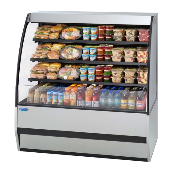
Installation & Operation Instructions
Refrigerated SSRPF & SSRVS Models
Federal Industries
215 Federal AVE
Belleville, WI 53508
Toll Free: (800) 356-4206
WI Phone: (608) 424-3331
Fax: (608) 424-3234
Table of
Contents
Previous
Page
Next
Page
1
2
3
4
5
Advertisement
Table of Contents
Need help?
Do you have a question about the SSRPF Series and is the answer not in the manual?
Ask a question
Questions and answers
Related Manuals for Federal SSRPF Series
Commercial Food Equipment Federal SSRC Series Installation & Operation Instructions
Refrigerated (46 pages)
Commercial Food Equipment Federal SSRC Installation & Operation Instructions
(43 pages)
Commercial Food Equipment Federal SSRVS Series Installation & Operation Instructions
(39 pages)
Commercial Food Equipment Federal SSRPF5052 Installation & Operation Instructions
(39 pages)
Commercial Food Equipment Federal SSRC3652 120V Installation & Operation Instructions
Refrigerated (46 pages)
Commercial Food Equipment Federal SSRC5052 240V Installation & Operation Instructions
Refrigerated (46 pages)
Commercial Food Equipment Federal SSRSP Series Installation & Operation Instructions
Refrigerated sandwich prep case (36 pages)
Commercial Food Equipment Federal 90 Series Troubleshooting Manual
(43 pages)
Commercial Food Equipment Federal SN4CD Installation & Operation Instructions
Self-contained & remote models (26 pages)
Commercial Food Equipment Federal SN4HD Installation & Operation Instructions
Hot deli displays (21 pages)
Commercial Food Equipment Federal CGR3I48 Installation & Operation Instructions
Self-contained & remote refrigerated, including dual zone & cold deli & non-refrigerated displays (65 pages)
Commercial Food Equipment Federal FCCR-4 Installation & Operation Instructions
(27 pages)
Commercial Food Equipment Federal Vision VRSS-MLK Series Installation & Operation Instructions
(55 pages)
Commercial Food Equipment Federal VRSS Series Installation & Operation Instructions
Self-contained & remote refrigerated (38 pages)
Commercial Food Equipment Federal ITH Installation & Operation Instructions
(32 pages)
Commercial Food Equipment Federal BENCHSTAR AT-938E User Manual
Electric salamander (7 pages)
This manual is also suitable for:
Ssrvs series
Ssrvs3633
Ssrvs5033
Ssrpf5052
Ssrvs5042
Ssrpf3652
...
Show all
Ssrpf5952
Ssrvs5942
Ssrvs3642
Ssrvs5933
Ssrpf7752
Ssrvs7742
Ssrvs7733
Ssrpf
Ssrvs
Table of Contents
Print
Rename the bookmark
Delete bookmark?
Delete from my manuals?
Login
Sign In
OR
Sign in with Facebook
Sign in with Google
Upload manual
Upload from disk
Upload from URL


Need help?
Do you have a question about the SSRPF Series and is the answer not in the manual?
Questions and answers