Table of Contents
Advertisement
Quick Links
E3335
REV. G – 12/27/18
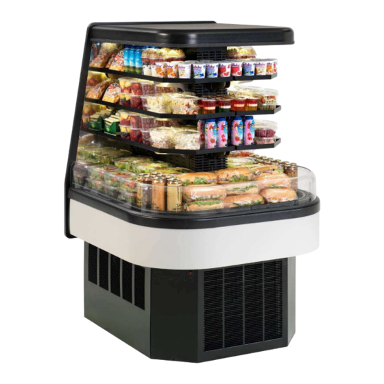
ECSS40 & ECSS60 MODELS
INSTALLATION & OPERATIONS MANUAL
KEEP THIS MANUAL FOR FUTURE REFERENCE
Engineering and technical data are subject to change without notice.
FEDERAL INDUSTRIES
Toll Free 1(800) 356-4206
ECSS E3335
FEDERAL INDUSTRIES
215 Federal AVE
WI Phone (608) 424-3331
Belleville, WI 53508
Fax: (608) 424-3234
- 1 -
Advertisement
Table of Contents

Related Manuals for Federal ECSS40


Summary of Contents for Federal ECSS40
- Page 1 E3335 REV. G – 12/27/18 FEDERAL INDUSTRIES ECSS40 & ECSS60 MODELS INSTALLATION & OPERATIONS MANUAL KEEP THIS MANUAL FOR FUTURE REFERENCE Engineering and technical data are subject to change without notice. FEDERAL INDUSTRIES 215 Federal AVE Belleville, WI 53508 Toll Free 1(800) 356-4206...
-
Page 2: Table Of Contents
CONTENTS INTRODUCTION ............................3 WARNING LABELS & SAFETY INSTRUCTIONS ................4 PRE-INSTALLATION PROCEDURES ....................5 INSPECTION FOR SHIPPING DAMAGE ................5 INSTALLATION INSTRUCTIONS......................5 LOCATING THE DISPLAY CASE ..................5 ELECTICAL CONNECTION ....................5-6 PERMANENT CONNECTED ..................... 5-6 CORD CONNECTED ......................6 REMOVING CASE FROM SHIPPING SKID ................ -
Page 3: Introduction
INTRODUCTION Thank you for purchasing a Federal Industries display case. This manual contains important instructions for installing and servicing the IMSS Models. A repair parts list and wiring diagrams are also included in the manual. Read all of these documents carefully before installing or servicing your case. -
Page 4: Warning Labels & Safety Instructions
This is important installation, operation, or service information. If you ignore the message, you may damage your case. The warning and safety labels shown throughout this manual are placed on your Federal Industries case at the factory. Follow all warning label instructions. If any warning or safety labels become lost or damaged, call our customer service department at 1(800) 356-4206 for replacements. -
Page 5: Pre-Installation Procedures
PRE-INSTALLATION PROCEDURES Inspection For Shipping Damage You are responsible for filing all freight claims with the delivering truck line. Inspect all cartons and crates for damage as soon as they arrive. If damage is noted to shipping crates, cartons, or if a shortage is found, note this on the bill of lading (all copies) prior to signing. -
Page 6: Cord Connected
Removal Section” of this manual for panel removal instructions. Remove electrical box cover to access electrical connection PERMANENT CONNECTION TERMINAL BLOCK PERMANENT CONNECTION ELECTRICAL BOX COVER 7/8 DIA ELEC FLOOR CONECTION Optional Top Electrical Entrance: The electrical connection box is accessible on the top of the case for ceiling drop electrical connection. -
Page 7: Removing Case From Shipping Skid
Removing Case From Shipping Skid CAUTION Do not push against the clear acrylic deflector around the sides and nose. Doing so can cause the acrylic to break. Do not lift or push on the top canopy located on top of the case. Doing so can permanently damage the tower frame. -
Page 8: Sealing The Unit To The Floor
SEALING THE UNIT TO FLOOR After the unit is positioned and the leg levelers are turned out, the unit needs to be sealed to the floor for NSF approved installation. Base Panel Removal DANGER: Electric shock hazard. Do not operate unit with panels removed. Panels must be in place when operating the case. -
Page 9: Base Component Layout Self Contained
Base Component Layout ECSS40SC Self Contained DATA PLATE CONDENSATE EVAPORATOR LOCATION OR OPTIONAL CONDENSATE PUMP CONDENSING LIGHT POWER SUPPLY COIL CONDENSING 7/8 FLOOR ELECTRICAL UNIT CONNECTION LOCATION 7/8 BACK PANEL ELECTRICAL CONNECTION LOCATION FOR OPTIONAL POWER CORD CONTROL PANEL LOCATION ELECTRICAL BOX POWER CONNECTION BOX Base Component Layout ECSS60SC Self Contained... -
Page 10: Base Component Layout Remote
Base Component Layout ECSS40R Remote REFRIGERATION FLOOR 7/8 BACK PANEL ELECTRICAL ACCESS COVER 12.1 CONNECTION LOCATION 3/8 LIQUID SOLENOID FOR OPTIONAL POWER CORD DATA PLATE LOCATION CONDENSATE PUMP SITE GLASS OPTIONAL 14.1 40.91 BASE FAN REFRIGERATION REAR ACCESS COVER 5/8 SUCTION LINE 7.01 CONTROL PANEL LOCATION... -
Page 11: Condensate Evaporator
Condensate Evaporator (if equipped) NOTICE: During normal defrost cycles, steam from the condensate evaporator may be visible around the case. The standard case is furnished with an electric condensate evaporator. Plumbing connections are not required. The condensate evaporator can be removed from the case and the condensate drain can be plumbed to a drain to conserve energy if desired. -
Page 12: Shelves
Shelves The ECSS has solid metal shelves with LED lighting as standard. There are (3) brackets required for each shelf (2) long brackets and (1) short brackets. The long brackets are for the long side of case and the short brackets are at the short end of case. - Page 13 3. Set the shelf on to the brackets and place the bracket retainer tip into slots on shelf. 4. Push shelf light cords into plastic shelf cord retainer clip located on inside of shelf bracket. 5. Remove the cap from the appropriate female light sockets. 6.
-
Page 14: Operating Instructions
OPERATING INSTRUCTIONS User Controls ELECTRONIC CONTROL / DISPLAY POWER SWITCH LIGHT SWITCH Power Switch The unit has a power switch that turns off power to the entire unit, including the condensate evaporator and the lights. This switch is located behind a lift up panel on the unit base. - Page 15 Button Overview Press and hold this button for 3 seconds to turn system on (if off) or off (if on). Also used to adjust set point when in set point adjust mode Press to enter set point adjust mode, confirm set point changes, and mute alarms.
- Page 16 Adjusting the set point The set point is what determines how cold the display case will hold food and beverage. To adjust the set point press and hold the button approx. 5 seconds until the display begins to flash a number. Then press the use the button to scroll number up (colder) or press the button to scroll number lower (warmer).
-
Page 17: Initial Start Up
Initial Start-Up After all the checks outlined in the installation section of this manual have been made, the case is ready to be put into service. Turn on the Power at the breaker box and flip the Power Switch and Light Switch on unit to the on position. At start up from a warm unit, it is recommended that the temperature control is set at a warm setting, such as 1. -
Page 18: Maintance
1. Disconnect power to the unit. 2. On ECSS40 Remove the nose panel and on ECSS60 remove the side panel on left side of case next to the controls. Carefully vacuum the front surface of condenser coil. Take care not to bend coil fins with vacuum cleaner nozzle. -
Page 19: Cleaning Instructions
CLEANING INSTRUCTIONS Acrylic Air Deflector Cleaning NOTICE: Clear acrylic air deflector requires special washing procedures to prevent hazing and yellowing of material. NEVER USE paper towels (wet or dry) for cleaning or drying and never use a dry towel. NEVER USE glass cleaner of any kind. Lightly dust (not wipe) surface with a damp Micro Fiber towel or chamois. -
Page 20: Weekly Cleaning
Weekly Cleaning NOTICE: Avoid splashing or soaking any electrical components with water to prevent electrical damage to the case. NOTICE: Shut off lights and power switches and remove all products from case. Allow sufficient time for the unit to reach room temperature before proceeding with cleaning. -
Page 21: Service Information
Service problems or request for repair parts from authorized service agencies, trained service personnel, or owners should be referred to: TECHNICAL SERVICE DEPARTMENT Federal Industries P.O. Box 290 Belleville, WI 53508 Toll Free: (800) 356-4206 / WI Phone (608) 424-3331... -
Page 22: Pre-Service Checklist
Pre-Service Checklist You may avoid the cost and inconvenience of an unnecessary service call by first reviewing this checklist of frequently encountered situations that can cause unsatisfactory case performance. CAUTION: Before servicing case, turn off power at the main breaker of fuse box. -
Page 23: Special Service Situations
If moisture or liquid is observed around or under a Federal Industries case, an immediate investigation should be made by qualified personnel to determine the source of the moisture or liquid. -
Page 24: Sale & Disposal
SALE & DISPOSAL If you the owner sells or gives away this Federal Industries case it is the owner’s responsibility to make sure that all safety labels and the Installation-Service Manual are included with it. If you need replacement labels or manuals, Federal Industries will provide them free of charge. -
Page 25: Control Operation
Control parameter changes can only be made by downloading a new set of parameters via a program chip supplied by Federal Industries. Operation The control uses two sensors, one located in the air stream and one located on the evaporator coil. -
Page 26: Refrigeration Operation
REFRIGERATION OPERATION Self Contained Models Refrigeration R404 Charge 6 Pounds The self-contained models are shipped from the factory with a completely operational 404A refrigeration system and require no modifications or adjustments upon installation. Case must be installed as per the installation section of this manual to provide proper condensing air cooling. Self Contained Refrigeration Operation The unit temperature is controlled by the Electronic control and timers outlined in the control section of this manual. - Page 27 1. Mount condensing unit indoors as close to the remote display case as practical. The refrigeration line should be as short as possible and must not exceed 30 feet. 2. All refrigeration and/or electrical materials between the condensing unit and display case are to be supplied by installing contractor.
-
Page 28: Replacement Parts
PARTS LIST Refrigeration System ECSS40 ECSS60 Condensing Unit Copeland (Self Contained) Before 8/1/14 30-19128 30-19025 Condensing Unit Copeland (Self Contained) After 8/1/14 30-19128 30-20047 Condensing Unit Tecumseh (Self Contained) Before 2/1/16 30-17889 30-20448 Condensing Unit Tecumseh (Self Contained) After 2/1/16... - Page 29 Temp Control - Remote (After 5/1/18) 32-19865-71 32-19865-71 Ribbon Cable - Display (Before 5/1/18) 32-19093 32-19093 Probe Temp (2) 32-19094 32-19094 Timer, Max Run (Before 5/23/12) 41-17324 41-17324 Condensate Pan Ass'y SA4889-1 SA4889-1 Heater Condensate Pan 40-17861 40-17861 Condensate evap pan 47-12963 47-12963 HighTemp Safety Ass'y...
-
Page 30: Wiring Drawing
Case Wiring Diagrams Self Contained ECSS40 SC Copeland BEFORE 5/23/12 91-19099 10/21/11 B/BL ECSS40 SC TOP LAMP COLOR CODE B/BL B/BL B/BL B = BLACK BL = BLUE G = GREEN TOP LAMP TOP LAMP W = WHITE Y = YELLOW... - Page 31 Self Contained ECSS40 SC Tecumseh BEFORE 5/23/12 91-19504 11/16/11 ECSS B/BL ECSS40 SC TOP LAMP MODELS ONLY COLOR CODE B/BL B/BL B/BL B = BLACK BL = BLUE G = GREEN TOP LAMP TOP LAMP W = WHITE Y = YELLOW...
- Page 32 Self Contained ECSS60SC BEFORE 5/23/12 IF OPTIONAL CONDENSATE PUMP OR 91-19453 12/19/11 IMSS60SC & ECSS60SC OPTIONAL CONDENSATE PAN ARE NOT USED CONDENSATE PUMP DISCARD WIRES B(22), R(23),G(24), R(22) R(23) POWER SUPPLY B/BL G(24) B/BL TOP LAMP ECSS ONLY B/BL B/BL B/BL SHELF LAMP TOP LAMP...
- Page 33 Remote ECSS40R BEFORE 5/23/12 91-19155 2/25/11 ECSS B/BL IMSS/ECSS REMOTE MODELS TOP LAMP ONLY COLOR CODE B/BL B/BL B/BL B = BLACK BL = BLUE G = GREEN TOP LAMP TOP LAMP W = WHITE Y = YELLOW R = RED IF OPTIONAL CONDENSATE PUMP OR B/BL B/BL...
- Page 34 Remote ECSS60R BEFORE 5/23/12 91-19454 1/2/12 IMSS60R & ECSS60R OPTIONAL CONDENSATE HEATER PAN POWER SUPPLY R(23) B/BL B(22) B/BL G(24) TOP LAMP ECSS ONLY B/BL B/BL B/BL SHELF LAMP TOP LAMP COLOR CODE B/BL B/BL B/BL B/BL B = BLACK BL = BLUE SHELF LAMP SHELF LAMP...
- Page 35 Self Contained ECSS40 SC Tecumseh Between 5/23/12-5/1/18 91-19504 8/26/14 ECSS B/BL MODELS TOP LAMP ECSS40SC TECHUMSEH ONLY COLOR CODE B/BL B/BL B/BL B = BLACK BL = BLUE G = GREEN TOP LAMP TOP LAMP W = WHITE Y = YELLOW...
- Page 36 Self Contained ECSS60SC used Between 5/23/12 & 8/1/14 IF OPTIONAL CONDENSATE PUMP OR 91-19630 5/23/12 IMSS60SC & ECSS60SC OPTIONAL CONDENSATE PAN ARE NOT USED CONDENSATE PUMP DISCARD WIRES B(22), R(23),G(24), R(22) R(23) POWER SUPPLY B/BL G(24) B/BL TOP LAMP ECSS ONLY B/BL B/BL B/BL...
- Page 37 Remote ECSS40R Between 5/23/12-5/1/18 91-19629 5/23/12 B/BL ECSS40R TOP LAMP COLOR CODE B/BL B/BL B/BL B = BLACK BL = BLUE G = GREEN TOP LAMP TOP LAMP W = WHITE Y = YELLOW R = RED IF OPTIONAL CONDO PUMP HOSE B/BL HEATER IS USED, TIE HEATER B/BL...
- Page 38 Remote ECSS60R Between 5/23/12-5/1/18 91-19631 5/23/12 IMSS60R & ECSS60R POWER SUPPLY B/BL B/BL TOP LAMP ECSS ONLY B/BL B/BL B/BL COLOR CODE SHELF LAMP TOP LAMP B = BLACK BL = BLUE W = WHITE Y = YELLOW B/BL B/BL B/BL B/BL G = GREEN...
- Page 39 Self Contained ECSS40SC -Between 5/1/18 & 12/15/18 91-19504-1 5/1/18 ECSS B/BL MODELS TOP LAMP ECSS40SC TECHUMSEH ONLY COLOR CODE B/BL B/BL B/BL B = BLACK BL = BLUE G = GREEN TOP LAMP TOP LAMP W = WHITE Y = YELLOW R = RED IF OPTIONAL CONDO PUMP HOSE B/BL...
- Page 40 Self Contained ECSS60SC -Between 5/1/18 & 12/15/18 IF OPTIONAL CONDO PUMP HOSE 91-20308-1 5/1/18 IMSS60SC & ECSS60SC SCROLL CONDENSATE PUMP HEATER IS USED, TIE HEATER WIRES TO B22 & R23 B(22) R(23) POWER SUPPLY B/BL G(24) B/BL TOP LAMP CONDENSATE PUMP ECSS ONLY STD ECSS B/BL...
- Page 41 Remote ECSS40R - Between 5/1/18 & 12/15/18 91-19629-1 5/1/18 B/BL ECSS40R TOP LAMP COLOR CODE B/BL B/BL B/BL B = BLACK BL = BLUE G = GREEN TOP LAMP TOP LAMP W = WHITE Y = YELLOW R = RED IF OPTIONAL CONDO PUMP HOSE B/BL B/BL...
- Page 42 Remote ECSS60R - Between 5/1/18 & 12/15/18 91-19631- 1 IMSS60R & ECSS60R - AFTER 5/1/18 POWER SUPPLY B/BL B/BL TOP LAMP ECSS ONLY B/BL B/BL B/BL COLOR CODE SHELF LAMP TOP LAMP B = BLACK BL = BLUE W = WHITE Y = YELLOW B/BL B/BL...
- Page 43 Self Contained ECSS40SC After - 12/15/18 91-19504-2 12/27/18 +B(RIB) ECSS40SC ITC LED TOP LAMP B/BL COLOR CODE +B(RIB) +B(RIB) B = BLACK BL = BLUE G = GREEN TOP LAMP TOP LAMP B/BL B/BL B/BL W = WHITE Y = YELLOW R = RED IF OPTIONAL CONDO PUMP HOSE +B(RIB)
- Page 44 Self Contained ECSS60SC AFTER 12/15/18 IF OPTIONAL CONDO PUMP HOSE CONDENSATE PUMP HEATER IS USED, TIE HEATER WIRES TO B22 & R23 B(22) R(23) B/BL G(24) +B(RIB) TOP LAMP B/BL CONDENSATE PUMP ECSS ONLY STD ECSS +B(RIB) +B(RIB) SHELF LAMP B/BL B/BL TOP LAMP...
- Page 45 Remote ECSS40R After - 12/15/18 91-19629-2 12/27/18 +B(RIB) ECSS40R ITC LED TOP LAMP B/BL COLOR CODE +B(RIB) +B(RIB) B = BLACK BL = BLUE G = GREEN TOP LAMP TOP LAMP B/BL B/BL B/BL W = WHITE Y = YELLOW R = RED IF OPTIONAL CONDO PUMP HOSE +B(RIB)
- Page 46 Remote ECSS60R After - 12/15/18 91-19631-2 12/27/18 IMSS60R, IMSS84R & ECSS60R ITC LED B/BL IF OPTIONAL CONDO PUMP HOSE HEATER IS USED, TIE HEATER +B(RIB) WIRES TO B22 & R23 TOP LAMP B/BL ECSS ONLY COLOR CODE +B(RIB) +B(RIB) B/BL B = BLACK BL = BLUE SHELF LAMP...
Need help?
Do you have a question about the ECSS40 and is the answer not in the manual?
Questions and answers