Furuno FMD-3100 Operator's Manual
Electronic chart display and information system (ecdis)
Hide thumbs
Also See for FMD-3100:
- Operator's manual (395 pages) ,
- Installation manual (110 pages) ,
- Instruction manual (103 pages)
Table of Contents
Advertisement
Quick Links
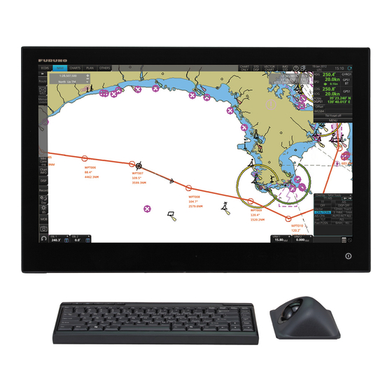
Electronic Chart Display and Information System (ECDIS)
English
Display Layout
Status bar
InstantAccess bar
(See page 3.)
Upper
section
Lower
section
Model
(See page 2.)
Chart scale/presentation mode box
Electronic chart area
Electronic chart area
Electronic chart area
EBL1 box,
Permanent warnings box
EBL2 box
Operator's Guide
FMD-3100
CLEAR
RADAR
Cursor position box
CLEAR
RADAR
Overlay/NAV
Tools box
VRM1 box,
VRM2 box
This guide provides the basic operating
procedures for this equipment. For detailed
information, see the Operator's Manual.
The brand and product names mentioned in this
guide are trademarks, registered trademarks or
service marks of their respective holders.
E
E
Sensor information box
E
E
Own ship functions box
Route information box
Turn Rate:
Alert box
Advertisement
Table of Contents

Subscribe to Our Youtube Channel
Related Manuals for Furuno FMD-3100


Summary of Contents for Furuno FMD-3100
- Page 1 Electronic Chart Display and Information System (ECDIS) procedures for this equipment. For detailed English information, see the Operator's Manual. The brand and product names mentioned in this FMD-3100 guide are trademarks, registered trademarks or Model service marks of their respective holders. Display Layout Status bar (See page 2.)
-
Page 2: Status Bar
Status Bar Status bar OTHERS: Sets system in standby; plays back data. PLAN: Selects the Voyage planning mode. CHARTS: Selects the Chart maintenance mode. NAVI: Selects the Voyage navigation mode. Display mode: No use. (Fixed at “ECDIS”.) How to open a drop-down list How to open a drop-down list Indicates a drop-down list. -
Page 3: Instant Access Bar
Instant Access Bar Upper section (by operating mode) Lower section Voyage navigation mode Chart maintenance mode NtoM Opens the Message SET: AUTO Load: dialog box to Shows, hides chart Starts automatic installation of the Chart Legend: manage AIS Safety features; sets chart chart data (CD or DVD ROM). - Page 4 Routes How to create a route WPT5 At last waypoint, Click a position 161.4° right-click and to mark a waypoint. 353.3NM select [Finish]. WPT6 Plan Route PLAN -ning WPT1 WPT1 WPT4 201.5° 309.0° 2137.2NM 971.4NM Click [New]. Click [New]. WPT2 106.9°...
- Page 5 Routes (con’t.) How to select a route to monitor To stop monitoring a route: To stop monitoring a route: 25 Apr 2016 25 Apr 2 25 Apr 2016 05 Apr 2016 05 Apr 2016 21 Mar 2016 02 Feb 2016 Route selected.
-
Page 6: User Charts
User Charts How to create a user chart Plan User PLAN -ning Chart Click [New]. Click [New]. Click object to draw. How to create a line How to create a line How to create a circle How to create a circle How to create an area How to create an area (1) Click... - Page 7 User Charts (con’t) How to select objects to display in user chart How to link a user chart to a route 24 Apr 2016 24 Apr 2016 12 Apr 2016 Symbol DISP Plan Route selected. DISP PLAN Route -ning Click [Select]. Click [Open].
- Page 8 Chart Operations How to control visibility of chart objects Basic Setting Control basic chart settings Chart DISP DISP Control chart objects Symbol DISP Control navigational features...
- Page 9 Chart Operations How to set safety contours and chart alerts Chart DISP Alert Set safety contour here. Click to select chart alert type: Click icon to switch between (Alarm): Audio+visual indications vice versa. (Warning): Visual indication (Caution): No indication To turn off display of a chart object in route monitoring, remove check mark from alert (alarm, warning, caution).
- Page 10 TT/AIS Operations How to find target info Click a target to show its information. Title bar TT Info (1/2) Title bar AIS Info (1/2) Click to switch level of detail TT No. Scroll buttons MMSI Scroll buttons AIS symbols (main) Vessel name TT symbols (main) Bearing...
-
Page 11: Radar Overlay
TT/AIS Operations (con’t) Radar Overlay Open the chart menu, select TT/AIS Setting and then Setting. The below menus can also Activates, deactivates the be displayed by clicking the radio button on the pop-up menu radar overlay. that appears when an item other than TT/AIS is selected on Adjusts the strength of radar echo. -
Page 12: Alert Icons And Their Meanings
Red triangle. Cross in center of triangle. alarm Presented together with icon numbers 1, 2 and 5. Acknowledge not allowed for Yellow-orange circle. Cross in center of warning circle. Presented together with icon numbers 6, 7 and 10. Pub. No. OSE-44840-D (1610, GREG) FMD-3100...
Need help?
Do you have a question about the FMD-3100 and is the answer not in the manual?
Questions and answers