
Related Manuals for ATO MF5000 Series


Summary of Contents for ATO MF5000 Series
- Page 1 ATO MF5000 Series MEMS Mass Flow Meters MEMS FLOW SENSING PRODUCTS User Manual (VC.2)
-
Page 2: Restriction On Use
Do not use this product in any environments where human safety may be at risk. Only a qualified person from ATO or a person who is accredited by ATO can perform troubleshooting services to the product, ATO is otherwise not liable for any consequences thereafter. -
Page 3: Table Of Contents
Contents RESTRICTION ON USE ..................SAFETY PRECAUSION ..................Contents ........................ 1 Overview ......................2 Models and Selection ..................3 Product Description ................... 4 Specifications ....................5 Installation ......................5.1 Physical Dimensions ..................5.2 Installation Instructions ................. 5.3 Attentions ..................... 6 Operation and Communication ................ -
Page 4: Overview
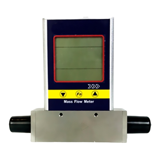
1. Overview MF5000 series mass flow meters are specially designed for small pipe flow monitoring and control. The series can measure gas flow in a pipe diameter as small as 3 mm, but not over 19 mm. With the self-flow conditioning feature of the MEMS sensor package, the meters feature an extremely low pressure loss compared to the traditional by-pass thermal mass flow meters in this application scope. -
Page 5: Models And Selection
MF50 Gas (A - air; C - CO ; N - N ; O - O ; R - Ar; for other gases, please contact ATO.) Display (D - with LCD display) Output (A - 4~20mA; B - RS485; D - pulse/ 0~5V;... -
Page 6: Specifications
4. Specifications ± Accuracy (1.5+0.5FS)%; Working Temperature -20~65 C; Working Pressure <1.5 MPa; ≤ Humidity 95%RH; Power supply 1 ~ 4 VDC 50mA; Interface 4~20mA/RS485/Pulse Mechanical Connection NPT; Display Mass flow, accumulated mass flow; Calibration Air@20 C, 101.325 kPa ( other gases upon request); Ex Proof Ex ia IIC T4 Protection... -
Page 7: Installation Instructions
5.2 Installation Instructions The product at the time of shipment is fully inspected for product quality and meets all safety requirements. Additional safety measures during the installation should be applied. This includes, but is not limited to leakage verification procedures, standard EDS (electrostatic discharge) precautions, DC voltage precautions, and heavy duty precautions. -
Page 8: Attentions
Flow Direction Flow Direction 40DN 40DN 10DN 10DN 40DN ( e ) 2 x 90 degree elbow, 3-dimensional ( f ) Control valve (iii)During installation, please make sure no any foreign materials (such as water, oil, dirty, particles, etc.) falling into the pipe. d) Connect electrical wires for LCD, and then electrical wires for inputs/outputs. -
Page 9: Operation And Communication
6. Operation and Communication 6.1 Cable Definition The electrical interfaces are defined as Figure 6-1: Pin Definition Color 4~20mA output Purple RS485(B) Brown User Interface DB-9 (Male) 4~20mA GND Colorless 1 2 3 4 5 Pulse output Yellow Pulse GND White N.C. -
Page 10: Setup Via Buttons
6.6 Setup via Buttons 6.6.1 Button definition Three buttons: Scroll up the setup menu Selection/confirmation of a setting Scroll down the setup menu 6.6.2 Operation (1) The user interface (Figure 6-6): Button is used for function selection. After press it, the menu asks for password (authentication mode). Figure 6-6 User Interface Figure 6-7 Password menu Figure 6-8 Function setup menu... - Page 11 “UnITTyPE” select instant flow un its. Press the display will show the instant flow units menu; if the value is “--n3--”, the instant flow unit is Nm /h; if the value is “--SL--”, the instant flow unit is SLPM. Press to switch in two units.
- Page 12 Normal display Push Input password Default :111 1 Push Correct? Push Quit Push Push Push Push Push Push Response time 4000ms Instant flow unit shows shows Push Push Push Push Push Push Push Response time Nm /h SLPM Instant flow unit shows shows 2000ms...
-
Page 13: Safety And Maintenance
If there are questions or doubts, please contact manufacturer immediately before further actions. Please ensure the DC power is off before disassembling the sensor. All maintenance of the sensor should be done by trained and certified personnel by ATO. -
Page 14: Warranty
365 days after a cause of action has accrued. The products returned under warranty to ATO shall be at user or purchaser's risk of loss, and will be returned, if at all, at ATO's risk of loss. Purchasers or users are deemed to have accepted this limitation of warranty and liability, which contains the complete and exclusive limited warranty of ATO, and it shall not be amended, modified or its terms waived except by ATO's sole action.
Need help?
Do you have a question about the MF5000 Series and is the answer not in the manual?
Questions and answers