Table of Contents
Advertisement
Quick Links
Advertisement
Table of Contents

Related Manuals for Array electronic 366X


Summary of Contents for Array electronic 366X
- Page 1 USER’S MANUAL SWITCHING-MODE DC POWER SUPPLY ARRAY 366X ARRAY ELECTRONIC...
- Page 2 ARRAY 366X SWITCHING-MODE DC POWER SUPPLY ARRAY 366X is a series of 500W programmable switching-mode DC power supplies with RS-232, USB (optional) and GPIB (optional) interfaces. The durability, good simple operation, low noise, excellent output accuracy as well as the adjustment from 0V make this series of reliable power supplies the right choice for many applications.
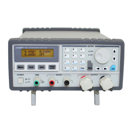
- Page 3 The Front Panel at a Glance 1. AC power switch 2. Sense terminals 3. Earth ground terminal 4. Supply output terminals 5. Output on/off key 6. Left/Right key 7. Control knob 8. Up/Down key 9. Menu setting key 10. Voltage setting key 11.
- Page 4 12. Switch key for second function : Enables the second function of other keys. 13. Store key for second function (Save): Stores the present operating states in location “0”, “1”, … “9”. 14. Recall key for second function (Recall): Recalls a previously stored operating state from location “0”, “1”,…“9”.
- Page 5 The output of power supply is in CC mode. The Rear Panel at a Glance 1. AC inlet 2. Fuse holder 3. RS-232 interface connector 4. GPIB or USB interface connector (optional) 5. Fan outlet An Introduction to this Manual General Information Apart from a general description of your power supply, it provides instructions for checking your power supply, selecting power-line voltage and connecting to AC...
- Page 6 Tutorial It describes basic operation of the power supply and gives specific details on the operation and use of ARRAY 366X power supplies. Specifications It lists the power supply’s basic specifications.
-
Page 7: Table Of Contents
Contents Chapter 1 General Information ……………………………………...... 11 General Information………………………………………………………………… 11 Safety Considerations………………………………………………….. ………… ...11 Description……………………………………………………………...... 11 Installation……………………………………………………………………………12 Initial Inspection……………………………………………………….......12 Mechanical Check……………………………………………………………………12 Electrical Check……………………………………………………………………12 Temperature Control………………………………………………………………… 12 Rack Mounting……………………………………………………………………….13 Chapter 2 Initial Operation ………………………………………………………..14 Initial Operation ……………………………………………………………………..14 Preliminary Checkout………………………………………………………………..14 Power-Line Cord……………………………………………………………………..14 Fuse Replacement……………………………………………………………………15 Power-On Checkout………………………………………………………….16 Self-test started……………………………………………………………….16... - Page 8 Enabling the outputs………………………………………………………………….23 Verifying that the power supply is in the constant current mode…………………..23 Menu Setting ………………………………………………………………………24 Main Menu Description…………………………………………………………….24 Storing and Recalling………………………………………………………………24 Error Messages Display…………………………………………………………….25 Local/ Remote Operation Switch…………………………………………………..25 Protection Function…………………………………………………………………26 Abnormal Latched State Clearance…………………………………………………26 Over-Voltage…………………………………………………………………………26 Over-Temperature…………………………………………………………………….26 The Power Supply Calibration……………………………………………………….27 Calibration Instrument………………………………………………………………..27 Cautions……………………………………………………………………………..27 Calibration Procedures………………………………………………………………27...
- Page 9 SCPI Confirmed Commands…………………………………………………….55 Device-Specific Commands………………………………………………………57 Chapter 5 Application Programs………………………………………………….58 Application Programs………………………………………………………………...58 RS-232 Operation Using QuickBACSIC ………………………………………….58 Chapter 6 Tutorial………………………………………………………………….59 Tutorial……………………………………………………………………………….59 An Overview of ARRAY 366X Operation…………………………………………59 Output Characteristics………………………………………………………………59 Unregulated State…………………………………………………………………….60 Unwanted Signals…………………………………………………………………….60 Connecting the Load………………………………………………………………..61 Output Isolation………………………………………………………………………61 Multiple Loads……………………………………………………………………..61 Remote Voltage Sensing……………………………………………………………...62 Considerations……………………………………………………………………….62...
- Page 10 Specifications………………………………………………………………………..64 Performance Specifications………………………………………………………….64 Transient Response Time……………………………………………………………65 Command Processing Time………………………………………………………….65 Supplemental Characteristics………………………………………………………65 APPENDIX Error Messages …………………………………………………67 Error Messages…………………………………………………………………….67 Execution Errors…………………………………………………………………….68 Self-Test Errors……………………………………………………………………….71 Calibration Errors ……………………………………………………………………71...
-
Page 11: Chapter 1 General Information
ARRAY 366X is a series of programmable switching-mode DC power supply with stable voltage and constant current. The excellent line and load regulation, extremely low ripple and noise make it well suited as a high preference power system. 366X, as a kind of high-efficient switching-mode supply, features wide supply input voltage from 100-240AC, high power factor and a minimum output of 0V. -
Page 12: Installation
* Calibration * Output on/off * System self-test This power supply is equipped with a liquid crystal display for displaying the output of voltage and current. A 5-digit voltage and a 5-digit current could show the actual or setting value of a selected supply simultaneously. And the liquid crystal display can show the current mode of power supply。... -
Page 13: Temperature Control
Temperature Control The power supply’s performance will not be affected when operating within the temperature range of 0°C to 40°C, and within the temperature range of 40°C to 55°C, the over-temperature protection may take effect, depending on the input voltage and output power. -
Page 14: Chapter 2 Initial Operation
Preliminary Checkout ARRAY 366X power supply can be used from a rated 100 V to 240 V single phase AC power source at 47 to 63 Hz. There is an indication below the AC power inlet on the rear panel showing the rated input voltage set for the power supply at the factory. -
Page 15: Fuse Replacement
Fuse Replacement 1 Replace the fuse Step 1: Remove the fuse-holder below AC power inlet. Step 2: Replace the fuse with the correct one that meets the requirements. Step 3: Put back the fuse holder. For 115V AC operation, 10AT fuse must be used; For 230V AC operation, 6AT fuse must be used. -
Page 16: Power-On Checkout
Power-On Checkout The power-on test includes an automatic self-test that checks the internal microprocessors and a system self-test after the power supply is turned on, and examines the information relate to self-test process shown on the front panel. You will observe the following sequence on the display: 1. -
Page 17: Output Checkout
Output Checkout The output checkout is to ensure that the power supply develops its rated outputs and properly responds to various operations. Specific steps are shown as followings: Voltage Output Checkout 1. Turn on the power supply. Press the “Power-on” button, and finish the power-on checkout. Usually the power supply will go into the power-on / reset state automatically. -
Page 18: Current Output Checkout
Current Output Checkout 1. Turn on the power supply. Press “Power-on” button and finish the power-on checkout. Usually the power supply will go into the power-on / reset state automatically and the “OFF” annunciator in the lower right corner of the LCD turns on. Both the voltage value and current value are 0. - Page 19 6. Ensure that the current can be adjusted from 0A to the maximum rated value. Adjust the knob until the ammeter indicates 0A and then until the ammeter indicates the maximum rated value. If an error has been detected during the output checkout procedures, the ERROR annunciator will turn on.
-
Page 20: Chapter 3 Front Panel Operation
Chapter 3 Front Panel Operation Front Panel Operation 3.1 Front Panel Operation Overview • Output on/off • Constant Voltage setting • Constant Current setting • Menu Setting • Storing and Recalling • Error Messages Display • Local/Remote Operation switch • Protection Function •Power Supply Calibration 3.2 Output on/off The output of the power supply could be switched on or off through this... -
Page 21: Constant Voltage Output Setting
When it is operated from remote interface, inputting the following command can enable or disable the output: OUTPUT ON/OFF. You can turn on the output by selecting ON and turn off the output by selecting OFF. 3.3 Constant Voltage Output Setting Constant voltage output is the most common output of the power supply. -
Page 22: Enabling The Outputs
① Press “ Iset” key to enter into current setting state. ② Input the desired current value by pressing number keys. “Clear” key can be used to clear the wrong value to input again. ③ Press “Enter” key to confirm the current setting value. 2). -
Page 23: Setting The Desired Output Current
2). Using “Left/Right” keys, knob and “Enter” key to input: ① Press “Vset” to enter into voltage setting state. ② Press “Left/Right” keys to move the blinking digit to the corresponding digit of the value. ③ Increase or decrease the relevant value by turning the knob clockwise or counter clockwise, then use “Left/Right”... -
Page 24: Menu Setting
3.4 Menu Setting 3.4.1 Main Menu Description Press “Menu” key to enter into main menu, which is showed as follows: Function and Parameter Description Current Limit: Current Limit: 14.600A Current Limit Value Voltage Limit: Voltage Limit: 35.200V Voltage Limit Value Voltage Over: Voltage Over:... -
Page 25: Error Messages Display
store case, voltage and current values are saved in corresponding EEPROM and for a recall condition, the voltage and current values stored previously can be retrieved from corresponding EEPROM and set as present values. Example 1: Set voltage to 5V and current to 2A. Then turn on the power supply and save this state to the EEPROM specified by Location 1. -
Page 26: Local/ Remote Operation Switch
3.8 Local/ Remote Operation Switch If it is need to operate the power supply from the keys and knobs in the front panel, the power supply must keep in local control state. And the power supply will stay in this state as soon as it is switched on. In remote control state, all keys and knobs become invalid (except “2nd”... -
Page 27: Over-Temperature
3.9.3 Over-Temperature If the internal temperature of the supply is above the safety limitation, over-temperature protection will be triggered; the supply output will turn off and OT is displayed. In the meantime, OT and PS in the Questionable Status Register will be set and keep in this state until they are reset and over-temperature state is removed. - Page 28 Input the password “003662”, then press “Enter” key to enter into calibration menu, which is shown as below: Select CV, CC or OV mode calibration by direction key. If “DEF” is selected, all calibration parameters are restored to default value. CV, CC and OV mode should be calibrated one by one, which is the correct calibration sequence.
- Page 29 Input the value you read from KEITHLEY 2000, which is retained to four decimal places. Press “Clear” key to remove the wrong input value of current digit. Then press “Enter” key to confirm. 3.1.4 34.5V Calibration Press “Enter” key to verify and then the display will show as follows: Input the value you read from KEITHLEY 2000, which is retained to four decimal places.
- Page 30 3.2.2 0.5A Calibration Press “Enter” key, you will see the following figure in the display: Input the value you read from , which is retained to four decimal places. FLUEK 45 Press “Clear” key to remove the wrong input value of present digit. Then press “Enter”...
-
Page 31: Chapter 4 Remote Interface Reference
When the calibration is completed, the display will go back to the calibration menu. Chapter 4 Remote Interface Reference Remote Interface Reference A detailed description of how to use the remote interface will be given in this chapter, which includes how to program the power supply through the remote interface, the commands format and matters need attention. -
Page 32: An Introduction To The Scpi Language
Each SCPI command presented in this section uses the following conventional format. 1. Square brackets ([ ]) indicate optional keywords or parameters. 2. Braces ({ }) enclose parameters within a command string. 3. Triangle brackets (< >) indicate that you must substitute a value or a code for the enclosed parameter. -
Page 33: Command Format Used In This Manual
[:AMPLitude]? [MIN|MAX] [SOURce:] is the root keyword of the command, CURRent and VOLTage are the second-level keywords, and LIMit is the third-level keywords. A colon ( : ) separates a command keyword from a lower-level keyword. Command Format Used in This Manual The format used to show commands in this manual is shown below: CURRent {<current>|MINimum|MAXimum} The command syntax shows most commands are the mixture of upper- and... -
Page 34: Command Separators
chosen by power supply. A colon “:” separates a command keyword from a lower-level keyword. You must insert a blank space to separate a parameter from a command keyword. If a command requires more than one parameter, you must separate adjacent parameters with a comma as shown below: SOURce:CURRent:TRIGgered APPL 3.5,1.5... -
Page 35: Querying Parameter Settings
Querying Parameter Settings You can query the value of most parameters by adding a question mark (?) to the command. For example, the following command sets the output current to 5A CURR 5 You can query the value by executing: CURR? You can also query the minimum or maximum value allowed with the present function as follows:... -
Page 36: Boolean Parameters
short form in all upper-case letters. The following command uses discrete parameters: TRIG:SOUR {BUS|IMM} Boolean Parameters: Boolean parameters represent a single binary condition that is either true or false. For a false condition, the power supply will accept “OFF” or “0”. For a true condition, the power supply will accept “ON”... -
Page 37: Trigger Commands
VOLTage[:LEVel]:TRIGgered[:AMPLitude] {<current>[MIN|MAX} VOLTage[:LEVel]:TRIGgered[:AMPLitude]? [MIN|MAX] Trigger Commands INITiate[:IMMediate] TRIGger[:SEQuence] :DELay {<second>|MIN|MAX} :DELay? :SOURce {BUS|IMM} :SOURce? *TRG System-Related Commands DISPlay[:WINDow] [:STATe] {OFF|ON} [:STATe]? :TEXT[:DATA] <quoted string > :TEXT[:DATA]? :TEXT:CLEar SYSTem :BEEPer[:IMMediate] :ERRor? :VERSion? *IDN? *RST *TST? *SAV {1|2|3} *RCL {1|2|3} Calibration Commands CALibration :COUNt? :CURRent[:DATA] <... -
Page 38: Status Reporting Commands
This chapter gives an overview of the basic commands used to program the power supply over the remote interface. Some of them are the SCPI-confirmed commands, and some are the device-specific commands. It is unnecessary to differentiate them when using ARRAY 366X. -
Page 39: Using The Low-Level Commands
Using the APPLy Command The APPLy command provides the most straightforward method to program the power supply over the remote interface, such as to control one output or triple outputs of power supply, and to read the immediate output value of each supply. Give the following example to illustrate: APPLY 3.3,2.0 Set the supply to an output of 3.3V rated at 2.0A... -
Page 40: Output Setting And Operation Commands
INIT Initiate the trigger system Using the APPLY Command APPLy {<voltage>|DEF|MIN|MAX}[,{<current>|DEF|MIN|MAX}]] This command is to specify the power supply’s output, which can be divided into three parts: The first part is the keyword “APLLy”. The second part is to set the voltage value {<voltage>|DEF|MIN|MAX}, by which you can set the output voltage value of the specified supply. -
Page 41: Measurement Commands
program the output of power supply, the low-level commands give you more flexibility to change individual parameters, which include output selection commands, measurement commands, output on/off and tracking operation commands and output setting commands. Measurement Commands MEASure:CURRent[:DC]? This command measures and returns the current value at the present output terminals of the power supply. - Page 42 CURR? MAX Query and return the maximum programmable current level of the output terminals. CURR? MIN Qurery and return the minimum programmable current level of the output terminals [SOURce:]CURRent[:LEVel]:LIMit[:AMPLitude] {<current>|MIN|MAX|DEF} This command is to set the maximum current limit value of the output selected with INST command.
-
Page 43: Trigger Source Choice
VOLT? MAX Query and return the maximum programmable voltage levels of the output terminals VOLT? MIN Query and return the minimum programmable voltage levels of the output terminals [SOURce:]VOLTage[:LEVel]:LIMit[:AMPLitude] {<voltage>|MIN|MAX|DEF} This command is to set the maximum voltage limit value of the presently programmed output selected with INST command. -
Page 44: Bus (Software) Triggering
4. Execute an INITiate[:IMMediate] command. If the IMMediate source is selected, the selected output is set to the triggered level immediately. But if the trigger source is the bus, the power supply is set to the triggered level after receiving the Group Execute Trigger (GET) or *TRG command. -
Page 45: System-Related Commands
TRIGger[:SEQuence]:SOURce {BUS | IMMediate} This command selects the source from which the power supply will accept a trigger. The power supply will accept a bus trigger or an internal immediate trigger. At *RST, the bus trigger source is selected. TRIGger[:SEQuence]:SOURce? This command queries the present trigger source and returns “BUS”... - Page 46 exit the character string displaying mode to switch to the immediate mode automatically. SYSTem:BEEPer[:IMMediate] This command makes the power supply generates a single beep immediately. SYSTem:ERRor? This command queries the power supply’s error queue. When “ERROR” annunciator in the front panel turns on, one or more command syntax or hardware errors have been detected.
-
Page 47: Calibration Commands
VOLT[:LEV]:TRIG The reset operation sets the output current to the maximum value. *TST? This query performs a complete self-test of the power supply and returns “0” if the self-test passes or “1” if it fails. *SAV { 0| 2 | ……|9 } This command stores the present state of the power supply, which can store 10 sets of operating states from 0 to 9. -
Page 48: Rs-232 Interface Commands
CALibration:SECure:STATe {OFF | ON>}, <code> This command secures or unsecures the power supply for calibration. CALibration:SECure:STATe? This command queries and returns the current secured state for calibration of the power supply. The returned parameter is “0” (unsecured) or “1” (secured). CALibration:STRing <quoted string>... -
Page 49: The Scpi Status Registers
Ctrl-C This command clears the operation in progress over remote interface and discards any pending output data. The SCPI Status Registers All SCPI instruments implement status registers in the same way. The status system records various instrument conditions in three register groups: the Status Byte register, the Standard Event register, and the Questionable Status register group. -
Page 50: The Questionable Status Register
QUEStionable Status Event Registers Enable Registers VOLTage CURRent Not used Not used Output Buffer TEMPerature Not used Not used “OR” Not used Not used OVERvoltage Not used Not used Not used Not used Not used Status Byte Not used Event Registers Enable Registers STAT:QUES? STAT:QUES:ENAB <value>... -
Page 51: The Standard Event Register
Decimal Definition Value The power supply is abnormal in 0(Voltage) constant voltage mode. The power supply is abnormal in 1(Current) constant current mode. Always set to 0. 2-3(Not used) The fan has a fault condition. 4(Over-temperature) Always set to 0. 5-8(Not used) power supply... -
Page 52: The Status Byte Register
Bit Definitions - Standard Event Register Decimal Definition Value Operation Complete. All commands prior to and including an *OPC command have been executed. 1 not used Always set to 0. Query Error. The power supply tried to read the output buffer but it was empty. Or, new command line was received before a previous query had been read. -
Page 53: Status Reporting Commands
summary register are not latched. Clearing an event register will clear the corresponding bits in the status byte summary register. Reading all messages in the output buffer, including any pending queries, will clear the message available bit. Bit Definitions - Status Byte Summary Register Decimal Definition Value... - Page 54 returned is the first error that was stored. When you have read all errors from the queue, the “ERROR” annunciator turns off. 2. If more than 20 errors have occurred, the last error stored in the queue (the most recent error) is replaced with -350, “Too many errors”. No additional errors are stored until you read or remove errors from the queue.
-
Page 55: Scpi Conformance Information
after the command is executed. *PSC { 0 | 1 } (Power-on status clear.) This command clears the status byte and the standard event register enable masks when power is turned on (*PSC 1). When *PSC 0 is in effect, the status byte and standard event register enable masks are not cleared when power is turned on. -
Page 56: Device-Specific Commands
[:WINDow][:STATe] {OFF|ON} [:WINDow][:STATe]? [:WINDow]:TEXT[:DATA] <quoted string > [:WINDow]:TEXT[:DATA]? [:WINDow]:TEXT:CLEar MEASure [:SCALar]:CURRent[:DC]? [:SCALar] :VOLTage[:DC]? OUTPUT [:STATe] {OFF/ON} [:STATE]? [SOURce:] CURRent[:LEVel][:IMMediate][:AMPLitude] {<current>|MIN|MAX} CURRent[:LEVel][:IMMediate][:AMPLitude]? [MIN|MAX] CURRent[:LEVel]:TRIGgered[:AMPLitude] {<current>|MIN|MAX} CURRent[:LEVel]:TRIGgered[:AMPLitude]?[MIN|MAX] VOLTage[:LEVel][:IMMediate][:AMPLitude] {<voltage>|MIN|MAX} VOLTage[:LEVel][:IMMediate][:AMPLitude]?[MIN:MAX] VOLTage[:LEVel]:TRIGgered[:AMPLitude] {<voltage>|MIN|MAX} VOLTage[:LEVel]:TRIGgered[:AMPLitude]?[MIN|MAX] STATus :QUEStionable[:EVENt]? :QUEStionable:CONDition? :QUEStionable:ENABle? :QUEStionable:ENABle <enable value> SYSTem :BEEPer[:IMMediate] :ERRor? :VERSion TRIGger... -
Page 57: Chapter 5 Application Programs
The following commands are specific to the ARRAY 366X power supply. However, these commands are designed with the SCPI Command in mind and they follow all of the syntax rules defined by the standard command. List as follow: APPLy [{<voltage>|DEF|MIN|MAX>}[,{<current>|DEF|MIN|MAX}]]... -
Page 58: Rs-232 Operation Using Quickbacsic
RS-232 Operation Using QuickBACSIC The following example shows how to send command instruction and receive command responses over the RS-232 interface using QuickBASIC. This program has been tested and can be used directly. RS-232 operation using QuickBACSIC ' clear the display LOCATE 1, 1 ' Set the cursor at the first line of the first row DIM Recv$(100) -
Page 59: An Overview Of Array 366X Operation
These supplies also exhibit low ripple and noise, the tolerance of ambient temperature changes, circuit simplicity, and a high reliability. The ARRAY 366X is controlled by a control circuit that provides voltages to program the outputs. The power supply sends the output voltages back to the control circuit. -
Page 60: Unregulated State
The actual power supply has finite noise across the output terminals and finite noise from either terminal to earth ground. And the noise across the output terminals is of very low value in the ARRAY 366X. -
Page 61: Connecting The Load
The noise from the terminals to earth ground can be a problem for very sensitive circuitry that is referenced to earth ground. When a circuit is referenced to earth ground, a low level line-related AC current will flow from the output terminals to earth ground. -
Page 62: Considerations
leads. If the sense terminals (S+ and S-) are left open as shown in Figure A, the voltage at the output terminals will increase approximately by 1 to 3% over the programmed value. And the feedback voltage will not indicate this increase. The dashed lines in Figure B illustrate remote sense connections. -
Page 63: Inductive Load
Extending the output The ARRAY 366X provides corresponding outputs, and enables the power supply to provide voltages or currents greater than its rated maximum outputs with different connecting measures when needed. - Page 64 the humidity and temperature will affect the reliability. The lower the temperature of the components is, the better the reliability is. When the power supply is in operation, an internal fan installed in the rear of power supply can keep the temperature of components low.
-
Page 65: Chapter 7 Specifications
Chapter 7 Specifications Specifications The performance specifications of ARRAY 366X are listed in this chapter in details (Specifications are warranted in the temperature range of 25±2℃ with a resistive load.). Please consult the relevant data in actual use. Performance Specifications... -
Page 66: Transient Response Time
Current Readback Resolution Voltage Current Meter Resolution Voltage 10mV 10mV Current Transient Response Time Less than 1ms for output to recover to within 100 mV following a change in output current from full load to half load or vice versa Command Processing Time Programming Commands: Maximum time for output to change after receiving APPLy and SOURce commands: <50msec... -
Page 67: Appendix Error Messages
Maximum time required for output voltage to settle within 10%-90% of its total excursion (for resistive load). Command processing time is excluded. 3661A 3662A 3663A 3664A 3665A Full load Up 50msec 50msec 50msec 60msec 60msec Full load Down 50msec 50msec 50msec 60msec 60msec... -
Page 68: Error Messages
Error Messages When the front-panel ERROR annunciator turns on, and the power supply generates a short beep, one or more command syntax or hardware errors have been detected. A record of up to 20 errors is stored in the power supply’s memory. Errors are stored and retrieved in first-in-first-out (FIFO) order. - Page 69 with a blank space. Example: TRIG:SOUR,BUS or APPL P6V 1.0 1.0 -104 Data type error The wrong parameter type was found in the command string. You may have specified a number where a string was expected, or vice versa. -108 Parameter not allowed More parameters were received than expected for the command.
- Page 70 -138 Suffix not allowed A suffix was received following a numeric parameter which does not accept a suffix. Example: STAT:QUES:ENAB 18 SEC (SEC is not a valid suffix). -144 Character data too long The character data element contained too many characters. -151 Invalid string data An invalid character string was received.
-
Page 71: Self-Test Errors
output buffer is cleared when power has been off, or after a *RST (reset) command has been executed. -420 Query UNTERMINATED The power supply was addressed to talk (i.e., to send data over the interface) but a command has not been received which sends data to the output buffer. For example, you may have executed an APPLy command (which does not generate data) and then attempted an ENTER statement to read data from the remote interface. - Page 72 Code Explanation Cal secured The calibration is secured. Invalid secure code An invalid calibration security code was received when attempting to unsecure or secure the power supply. You must use the same security code to unsecure the power supply as what was used to secure it, and vice versa. The security code may contain up to 12 alphanumeric characters.
- Page 73 Cal checksum failed, store/recall data in location 9 VER:20150323...
Need help?
Do you have a question about the 366X and is the answer not in the manual?
Questions and answers