Table of Contents
Advertisement
Quick Links
Advertisement
Table of Contents

Related Manuals for Array electronic 367 Series


Summary of Contents for Array electronic 367 Series
- Page 1 USER’S MANUAL SWITCHING-MODE DC POWER SUPPLY ARRAY 367X ARRAY ELECTRONIC...
- Page 2 ARRAY 367X SWITCHING-MODE DC POWER SUPPLY ARRAY 367X is a series of 800W programmable switching-mode DC power supplies with RS-232, USB (optional) and GPIB (optional) interfaces. The durability, good simple operation, low noise, excellent output accuracy as well as the adjustment from 0V make this series of reliable power supplies the right choice for many applications.
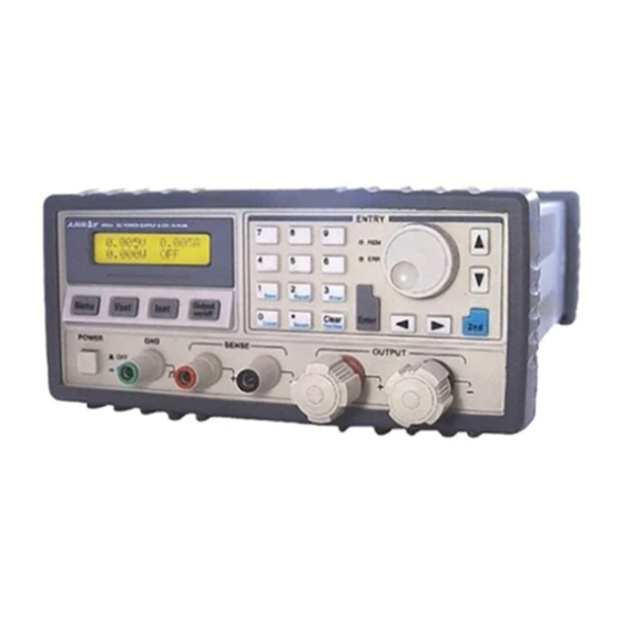
- Page 3 The Front Panel at a Glance 1. AC power switch 2. Sense terminals 3. Earth ground terminal 4. Supply output terminals 5. Output on/off key 6. Left/Right key 7. Control knob 8. Up/Down key 9. Menu setting key 10. Voltage setting key 11.
- Page 4 12. Switch key for the second function : Enables the second function of other keys. 13. Store key for the second function (Save): Stores the present operating states in location “0”, “1”, … “9”. 14. Recall key for the second function (Recall): Recalls a previously stored operating state from location “0”, “1”,…“9”.
- Page 5 The output of power supply is in CC mode. The Rear Panel at a Glance 1. AC inlet 2. Fuse holder 3. RS-232 interface connector 4. GPIB or USB interface connector (optional) 5. Fan outlet An Introduction to this Manual General Information Apart from a general description of your power supply, it provides instructions for checking your power supply, selecting power-line voltage and connecting to AC...
- Page 6 Tutorial It describes basic operation of the power supply and gives specific details on the operation and use of ARRAY 367X power supplies. Specifications It lists the power supply’s basic specifications.
-
Page 7: Table Of Contents
Contents Chapter 1 General Information ……………………………………...... 11 General Information………………………………………………………………… 11 Safety Considerations………………………………………………….. ………… ...11 Description……………………………………………………………...... 11 Installation……………………………………………………………………………12 Initial Inspection……………………………………………………….......12 Mechanical Check……………………………………………………………………12 Electrical Check……………………………………………………………………12 Temperature Control………………………………………………………………… 12 Rack Mounting……………………………………………………………………….13 Chapter 2 Initial Operation ………………………………………………………..14 Initial Operation ……………………………………………………………………..14 Preliminary Checkout………………………………………………………………..14 Power-Line Cord……………………………………………………………………..14 Fuse Replacement……………………………………………………………………15 Power-On Checkout………………………………………………………….16 Self-test started……………………………………………………………….16... - Page 8 Enabling the outputs………………………………………………………………….23 Verifying that the power supply is in the constant current mode…………………..23 Menu Setting ………………………………………………………………………24 Main Menu Description…………………………………………………………….24 Storing and Recalling………………………………………………………………24 Error Messages Display…………………………………………………………….25 Local/ Remote Operation Switch…………………………………………………..25 Protection Function…………………………………………………………………26 Abnormal Latched State Clearance…………………………………………………26 Over-Voltage…………………………………………………………………………26 Over-Temperature…………………………………………………………………….26 The Power Supply Calibration……………………………………………………….27 Calibration Instrument………………………………………………………………..27 Cautions……………………………………………………………………………..27 Calibration Procedures………………………………………………………………27...
- Page 9 Output Setting Commands………………………………………………………….41 Trigger Source Choice………………………………………………………………43 Bus (Software) Triggering…………………………………………………………43 Immediate Triggering……………………………………………………………….44 Trigger Commands……………………………………………………………….44 System-Related Commands………………………………………………………….44 Calibration Commands……………………………………………………………….47 RS-232 Interface Commands………………………………………………………48 The SCPI Status Registers…………………………………………………………48 What is an Event Register?..................48 What is an Enable Register?..................49 The Questionable Status Register……………………………………………………50 The Standard Event Register…………………………………………………………51 The Status Byte Register……………………………………………………………53 Status Reporting Commands……………………………………………………….53 SCPI Conformance Information……………………………………………………55...
- Page 10 Command Processing Time………………………………………………………….65 Supplemental Characteristics………………………………………………………65 APPENDIX Error Messages …………………………………………………67 Error Messages…………………………………………………………………….67 Execution Errors…………………………………………………………………….67 Self-Test Errors……………………………………………………………………….70 Calibration Errors ……………………………………………………………………71...
-
Page 11: Chapter 1 General Information
Chapter 1 General Informatio General Information This chapter provides a general description of your power supply. And it also contains instructions relate to initial inspection, selecting the power-line voltage, and connecting your power supply to AC power. Safety Considerations This power supply is a safety instrument with a protective earth terminal. The terminal must be connected to earth ground through a power source with a 3-wire ground receptacle when being connected to AC power supply. -
Page 12: Installation
This power supply is equipped with a liquid crystal display for displaying the output of voltage and current. A 5-digit voltage and a 5-digit current could show the actual or setting value of a selected supply simultaneously. And the liquid crystal display can show the current mode of power supply。... -
Page 13: Rack Mounting
the over-temperature protection may take effect, depending on the input voltage and output power. A brushless fan is used to cool the power supply by drawing cool air through the two sides and exhausting the heat through the fan outlet on the rear panel. Sufficient space must be left at the rear and two sides of the cabinet for air circulation when the power supply is installed. -
Page 14: Chapter 2 Initial Operation
Chapter 2 Initial Operation Initial Operation This chapter mainly focuses on three basic tests which should be performed before the operation of the power supply: the preliminary checkout, the power-on checkout, and the output checkout. The preliminary checkout is to check if the power supply could run correctly. -
Page 15: Fuse Replacement
Fuse Replacement 1 Replace the fuse Step 1: Remove the fuse-holder below AC power inlet. Step 2: Replace the fuse with what meets the requirements. Step 3: Put back the fuse holder. For 180V-265V AC operation, 10AT fuse is used. -
Page 16: Power-On Checkout
Power-On Checkout The power-on test includes an automatic self-test that checks the internal microprocessors and a system self-test after the power supply is turned on, and examines the information relate to self-test process shown on the front panel. You will observe the following sequence on the display: 1. -
Page 17: Output Checkout
Output Checkout The output checkout is to ensure that the power supply develops its rated outputs and properly responds to various operations. Specific steps are shown as followings: Voltage Output Checkout 1. Turn on the power supply. Press the “Power-on” button, and finish the power-on checkout. Usually the power supply will go into the power-on / reset state automatically. -
Page 18: Current Output Checkout
Current Output Checkout 1. Turn on the power supply. Press “Power-on” button and finish the power-on checkout. Usually the power supply will go into the power-on / reset state automatically and the “OFF” annunciator in the lower right corner of the LCD turns on. Both the voltage value and current value are 0. - Page 19 6. Ensure that the current can be adjusted from 0A to the maximum rated value. Adjust the current value to 0A and then gradually to the maximum rated value with the knobs or keys. If an error has been detected during the output checkout procedures, the ERROR annunciator will turn on.
-
Page 20: Chapter 3 Front Panel Operation
Chapter 3 Front Panel Operation Front Panel Operation 3.1 Front Panel Operation Overview • Output on/off • Constant Voltage setting • Constant Current setting • Menu Setting • Storing and Recalling • Error Messages Display • Local/Remote Operation switch • Protection Function •Power Supply Calibration 3.2 Output on/off The output of the power supply could be switched on or off through this... -
Page 21: Constant Voltage Output Setting
When it is operated from remote interface, inputting the following command can enable or disable the output: OUTPUT ON/OFF. You can turn on the output by selecting ON and turn off the output by selecting OFF. 3.3 Constant Voltage Output Setting Constant voltage output is the most common output of the power supply. -
Page 22: Enabling The Outputs
1). Using number keys and “Enter” key to input: ① Press “ Iset” key to enter into current setting state. ② Input the desired current value by pressing number keys. “Clear” key can be used to clear the wrong value to input again. ③... -
Page 23: Setting The Desired Output Current
2). Using “Left/Right” keys, knob and “Enter” key to input: ① Press “Vset” to enter into voltage setting state. ② Press “Left/Right” keys to move the blinking digit to the corresponding digit of the value. ③ Increase or decrease the relevant value by turning the knob clockwise or counter clockwise, then use “Left/Right”... -
Page 24: Menu Setting
3.4 Menu Setting 3.4.1 Main Menu Description Press “Menu” key to enter into main menu, which is showed as follows: Function and Parameter Description Current Limit: Current Limit: 14.600A Current Limit Value Voltage Limit: Voltage Limit: 35.200V Voltage Limit Value Voltage Over: Voltage Over:... -
Page 25: Error Messages Display
3 Press “Enter” key to confirm and exit store or recall menu simultaneously. For a store case, voltage and current values are saved in corresponding EEPROM and for a recall condition, the voltage and current values stored previously can be retrieved from corresponding EEPROM and set as present values. -
Page 26: Protection Function
If it is need to operate the power supply from the keys and knobs in the front panel, the power supply must keep in local control state. And the power supply will stay in this state as soon as it is switched on. In remote control state, all keys and knobs become invalid (except “2nd”... -
Page 27: The Power Supply Calibration
set and keep in this state until they are reset and over-temperature state is removed. You can’t clear the abnormal latched state until the supply temperature falls to its normal range. The Power Supply Calibration Because various factors may cause the reduction of the power supply’s output precision after it has been used for a period of time, the user should calibrate the power supply’s output to make the output return to the previous precision. - Page 28 Select CV, CC or OV mode calibration by direction key. If “DEF” is selected, all calibration parameters are restored to default value. CV, CC and OV mode should be calibrated one by one, which is the correct calibration sequence. Return to calibration menu after each mode calibration is completed.
- Page 29 places. Press “Clear” key to remove the wrong input value of current digit. Then press “Enter” key to confirm. 3.1.4 34.5V Calibration Press “Enter” key to verify and then the display will show as follows: Input the value you read from KEITHLEY 2000, which is retained to four decimal places.
- Page 30 Input the value you read from , which is retained to four decimal places. FLUEK 45 Press “Clear” key to remove the wrong input value of present digit. Then press “Enter” key to confirm. 3.2.3 6A Calibration Press “Enter” key to verify and then you will see the followings: Input the value you read from , which is retained to four decimal places.
-
Page 31: Chapter 4 Remote Interface Reference
Chapter 4 Remote Interface Reference Remote Interface Reference A detailed description of how to use the remote interface will be given in this chapter, which includes how to program the power supply through the remote interface, the commands format and matters need attention. SCPI Command Summary Simplified Programming Overview Using the Apply Command... -
Page 32: An Introduction To The Scpi Language
4. A vertical bar ( | ) separates one of two or more alternative parameters. An Introduction to the SCPI Language SCPI (Standard Commands for Programmable Instruments) is an ASCII-based instrument command language designed for test and measurement instruments. The detailed techniques used to program the power supply over the remote interface are introduced in the following sections. -
Page 33: Command Format Used In This Manual
Command Format Used in This Manual The format used to show commands in this manual is shown below: CURRent {<current>|MINimum|MAXimum} The command syntax shows most commands are the mixture of upper- and lower-case letters. The upper-case letters indicate the abbreviated spelling for the command. -
Page 34: Command Separators
Command Separators A colon “ :” is used to separate a command keyword from a lower-level keyword as shown below: SOURce:CURRent:TRIGgered A semicolon “ ;” is used to separate two commands within the same subsystem as shown below: SOUR:VOLT MIN;CURR MAX The following two commands have the same effect as the above command. -
Page 35: Scpi Command Terminators
You can also query the minimum or maximum value allowed with the present function as follows: CURR? MAX CURR? MIN SCPI Command Terminators A command string sent to the power supply must terminate with a <new line> character. The IEEE-488 EOI (end-or-identify) message is interpreted as a <new line> character and can be used to terminate a command string in place of a <new line>... -
Page 36: Output Setting And Operation Commands
A string must begin and end with matching quotes; either with a single quote or with a double quote. You can include the quote delimiter as part of the string by typing it twice without any characters in between. The following command uses a string parameter: DISPlay:TEXT <quoted string>... -
Page 37: Calibration Commands
DISPlay[:WINDow] [:STATe] {OFF|ON} [:STATe]? :TEXT[:DATA] <quoted string > :TEXT[:DATA]? :TEXT:CLEar SYSTem :BEEPer[:IMMediate] :ERRor? :VERSion? *IDN? *RST *TST? *SAV {1|2|3} *RCL {1|2|3} Calibration Commands CALibration :COUNt? :CURRent[:DATA] < numeric value > :CURRent:LEVel {MIN|MAX} :SECure:CODE <new code > :SECure:STATe {OFF|ON},<new code> :SECure:STATe? :STRing <quoted string >... -
Page 38: Rs-232 Interface Commands
:INSTrument:ISUMmary<n>:ENABle? SYSTem:ERRor? *CLS *ESE <enable value> *ESE? *ESR? *OPC *OPC? *PSC {0|1} *PSC? *SRE <enable value> *SRE? *STB? *WAI RS-232 Interface Commands SYSTem :LOCal :REMote :RWLock Simplified Programming Overview This chapter gives an overview of the basic commands used to program the power supply over the remote interface. -
Page 39: Selecting A Trigger Source
VOLT 3.3 CURR 2.0 The two commands shown in this example has the same function as the first command shown in the above example, which shows when some individual parameter is changed, there is no need to enter the whole setting parameters as the above example, just enter some specified parameter. -
Page 40: Output Setting And Operation Commands
The third part is to set the current value {<current>|DEF|MIN|MAX}, by which you can set the output current value of the specified supply. For the setting range, please consult the relevant current parameters listed in the table of “Programming Ranges and Output Identifiers”... -
Page 41: Output On/Off And Tracking Operation Commands
Output on/off and Tracking Operation Commands Output[:STATe] {OFF|ON} This command enables or disables the outputs of the power supply. For example: OUTPUT ON Enable the outputs OUTPUT OFF Disable the outputs Output[:STATe]? This command queries the output state of the power supply and returns the corresponding values. - Page 42 This command programs the pending triggered current level of the power supply, which is a stored value and transferred to the output terminals when a trigger occurs. A pending triggered level is not affected by subsequent CURRent commands. [SOURce:]CURRent[:LEVel]:TRIGgered[:AMPLitude]? [MIN|MAX] This query checks and returns the presently programmed triggered current level.
-
Page 43: Trigger Source Choice
A pending triggered level is not affected by subsequent VOLTage commands. [SOURce:]VOLTage[:LEVel]:TRIGgered[:AMPLitude]? [MIN|MAX] This query checks and returns the presently programmed triggered voltage level. If no triggered level is programmed, the VOLTage value is returned. VOLTage:TRIGgered? Return the VOLTage value or the set triggered voltage level of the selected output VOLTage:TRIGgered? MAX Return the maximum programmable voltage values of the selected output... -
Page 44: Immediate Triggering
And the power supply outputs specified triggered output level after the set time delay if any delay is given. 3. You can also select the trigger source from the USB, RS-232 or GPIB interface. The operation has been introduced before. Immediate Triggering 1. - Page 45 This command turns the front-panel display on or off. When the display is turned off, messages are not sent to the display and all annunciators are disabled except the “ERROR” and “Rmt” annunciators. The display state is automatically turned on when you return to the local mode. After pressing the “Local”...
- Page 46 1995.0). *IDN? This query command reads the power supply’s identification string. The power supply returns four fields separated by commas. The first field is the manufacturer’s name, the second field is the model number, the third field is reserved (always “0”), and the fourth field is a version code which contains three numbers.
-
Page 47: Calibration Commands
Calibration Commands CALibration:COUNt? This command queries the power supply to determine the number of times it has been calibrated. CALibration:CURRent[:DATA] <numeric value> This command can only be used after calibration is unsecured. It enters a current value of a selected output that you obtained by reading an external meter. You must first select a calibration level (CAL:CURR:LEV) for the value being entered. -
Page 48: Rs-232 Interface Commands
entered. The power supply then computes new voltage calibration constants, which are then stored in internal memory. CALibration:VOLTage:LEVel {MINimum | MAXimum} Before using this command, you must select the output which is to be calibrated by INSTrument command. This command can only be used after calibration is unsecured. It sets the power supply to a calibration point that is entered with CALibration:VOLTage[:DATA] command. -
Page 49: What Is An Enable Register
or by sending the *CLS command. A reset (*RST) or device clearance command will not clear bits in event registers. Querying an event register returns a decimal value which corresponds to the binary-weighted sum of all bits set in the register. What is an Enable Register? An enable register defines which bits in the corresponding event register are logically ORed together to form a single summary bit. -
Page 50: The Questionable Status Register
QUEStionable Status Event Registers Enable Registers VOLTage CURRent Not used Not used Output Buffer TEMPerature Not used Not used “OR” Not used Not used OVERvoltage Not used Not used Not used Not used Not used Status Byte Not used Event Registers Enable Registers STAT:QUES? STAT:QUES:ENAB <value>... -
Page 51: The Standard Event Register
Decimal Definition Value The power supply is abnormal in 0(Voltage) constant voltage mode. The power supply is abnormal in 1(Current) constant current mode. Always set to 0. 2-3(Not used) The fan has a fault condition. 4(Over-temperature) Always set to 0. 5-8(Not used) power supply... - Page 52 Bit Definitions - Standard Event Register Decimal Definition Value Operation Complete. All commands prior to and including an *OPC command have been executed. 1 Not Used Always set to 0. Query Error. The power supply tried to read the output buffer but it was empty. Or, new command line was received before a previous query had been read.
-
Page 53: The Status Byte Register
output buffer, including any pending queries, will clear the message available bit. Bit Definitions - Status Byte Summary Register Decimal Definition Value 0-2 not used Always set to 0 One or more bits are set in the status 3 QUES register. - Page 54 2. If more than 20 errors have occurred, the last error stored in the queue (the most recent error) is replaced with -350, “Too many errors”. No additional errors are stored until you read or remove errors from the queue. If no errors have occurred when you execute this command, the power supply responds with “+0”, “No error”.
-
Page 55: Scpi Conformance Information
register enable masks when power is turned on (*PSC 1). When *PSC 0 is in effect, the status byte and standard event register enable masks are not cleared when power is turned on. *PSC? This command queries the power-on status clear setting. The returned parameter is “0”... -
Page 56: Device-Specific Commands
MEASure [:SCALar]:CURRent[:DC]? [:SCALar] :VOLTage[:DC]? OUTPUT [:STATe] {OFF/ON} [:STATE]? [SOURce:] CURRent[:LEVel][:IMMediate][:AMPLitude] {<current>|MIN|MAX} CURRent[:LEVel][:IMMediate][:AMPLitude]? [MIN|MAX] CURRent[:LEVel]:TRIGgered[:AMPLitude] {<current>|MIN|MAX} CURRent[:LEVel]:TRIGgered[:AMPLitude]?[MIN|MAX] VOLTage[:LEVel][:IMMediate][:AMPLitude] {<voltage>|MIN|MAX} VOLTage[:LEVel][:IMMediate][:AMPLitude]?[MIN:MAX] VOLTage[:LEVel]:TRIGgered[:AMPLitude] {<voltage>|MIN|MAX} VOLTage[:LEVel]:TRIGgered[:AMPLitude]?[MIN|MAX] STATus :QUEStionable[:EVENt]? :CONDition? QUEStionable :QUEStionable:ENABle? :QUEStionable:ENABle <enable value> SYSTem :BEEPer[:IMMediate] :ERRor? :VERSion TRIGger [:SEQuence]:DELay {<second>|MIN|MAX} [:SEQuence]:DELay? [:SEQuence]:SOURce{BUS|IMM} [:SEQuence]:SOURce? INITiate[:IMMediate] Device-Specific Commands The following commands are specific to the ARRAY 367X power supply. -
Page 57: Chapter 5 Application Programs
APPLy [{<voltage>|DEF|MIN|MAX>}[,{<current>|DEF|MIN|MAX}]] APPLy? CALibration :COUNt? :CURRent[:DATA] <numeric value> :CURRent:LEVel {MIN|MAX} :SECure:CODE <new code> :SECure:STATe {OFF|ON},<voltage> :SECure:STATe? :STRing <quoted string > :STRing? :VOLTage[:DATA] <numeric value> :VOLTage:LEVel {MIN|MAX} MEASure [:SCALar]:CURRent [:DC]? [:SCALar]:VOLTage[:DC]? [:SCALar]:TEMPerature? [SOURce:] CURRent[:LEVel]:LIMit[:AMPLitude] {<current>|MIN|MAX|DEF} CURRent[:LEVel]:LIMit[:AMPLitude]? {MIN|MAX|DEF} VOLTage[:LEVel]:LIMit[:AMPLitude] {<voltage>|MIN|MAX|DEF} VOLTage[:LEVel]:LIMit[:AMPLitude]? {MIN|MAX|DEF} SYSTem :LOCal :REMote... -
Page 58: Rs-232 Operation Using Quickbacsic
been tested and can be used directly. RS-232 operation using QuickBACSIC ' clear the display LOCATE 1, 1 ' Set the cursor at the first line of the first row DIM Recv$(100) ' Restore and receive the data array OPEN "COM1:9600, N, 8, 2, RS, LF, PE" FOR RANDOM AS #1 LEN = 1000 ' Baud Rate: 9600 ' Parity Check: None ' Data Bit: 8... -
Page 59: An Overview Of Array 367X Operation
on the lab bench or as a controlled power supply. This chapter gives specific details on the operation of the ARRAY 367X power supply. An Overview of ARRAY 367X Operation The ARRAY 367X has a very precise regulating properties and respond quickly to variations of the line and load. -
Page 60: Unregulated State
resistance value (compared to RC), the output voltage is at the voltage setting, and the output current is less than the current setting. In this case the power supply is in the constant-voltage (CV) mode and the current setting acts as a current limit. When the load RL is less than RC, the output current will dominate since the voltage will be less than the set voltage. -
Page 61: Connecting The Load
current flow multiplied by the impedance. To minimize this effect, the output terminal can be grounded at the output terminal. Alternately, any impedance to earth ground should have a complementary impedance to earth ground to cancel generated voltages. Connecting the Load Output Isolation The output of the power supply is isolated from earth ground and the power supply can be connected to the ground with the earth ground terminal when needed. -
Page 62: Inductive Load
with large capacitor may cause ringing in the power supply’s transient response. It is possible that certain combinations of load will result in output instability. And the problem may be solved by properly decreasing the total load capacitance. A large capacitor at the output terminals may cause the power supply to cross into CC or unregulated mode momentarily when the output is enabled. -
Page 63: Reliability
not turned on simultaneously. Reliability Reliability of the power supply depends heavily on the ambient condition, in which the humidity and temperature will affect the reliability. The lower the temperature of the components, the better the reliability. When the power supply is in operation, an internal fan installed in the rear of power supply can keep the temperature of components low. -
Page 64: Chapter 7 Specifications
Chapter 7 Specifications Specifications The performance specifications of ARRAY 367X are listed in this chapter in details (Specifications are warranted in the temperature range of 25±2℃ with a resistive load.). Please consult the relevant data in actual use. Performance Specifications 3672A 3673A 3674A... -
Page 65: Transient Response Time
Voltage Current Meter Resolution 1mV(@0-100V 1mV(@0-100 Voltage 10mV(@100-1 10mV(@100- 20V) 120V) Current Transient Response Time Less than 2ms for output to recover to within 100 mV following a change in output current from full load to half load or vice versa Command Processing Time Programming Commands: Maximum time for output to change after receiving APPLy and SOURce commands: <50msec... - Page 66 Voltage Programming Speed Maximum time required for output voltage to settle within 1% of its total excursion (for resistive load). Command processing time is excluded. 3672A 3673A 3674A 3675A Full load Up 50msec 50msec 60msec 60msec Full load Down 50msec 50msec 60msec 60msec...
- Page 67 Dimensions Clear Dimension Dimension with cover...
-
Page 68: Appendix Error Messages
APPENDIX Error Messages Error Messages When the front-panel ERROR annunciator turns on, and the power supply generates a short beep, one or more command syntax or hardware errors have been detected. A record of up to 20 errors is stored in the power supply’s memory. Errors are stored and retrieved in first-in-first-out (FIFO) order. - Page 69 -103 Invalid separator An invalid separator was found in the command string. You may have replaced a colon, semicolon, or blank space with a comma or you may have replaced a comma with a blank space. Example: TRIG:SOUR,BUS or APPL P6V 1.0 1.0 -104 Data type error The wrong parameter type was found in the command string.
-
Page 70: Self-Test Errors
A suffix for a numeric parameter contained too many characters. -138 Suffix not allowed A suffix was received following a numeric parameter which does not accept a suffix. Example: STAT:QUES:ENAB 18 SEC (SEC is not a valid suffix). -144 Character data too long The character data element contained too many characters. - Page 71 -410 Query INTERRUPTED A command was received which sends data to the output buffer, but the output buffer contained data from a previous command (the previous data is not overwritten). The output buffer is cleared when power has been off, or after a *RST (reset) command has been executed.
-
Page 72: Calibration Errors
Calibration Errors Code Explanation Cal secured The calibration is secured. Invalid secure code An invalid calibration security code was received when attempting to unsecure or secure the power supply. You must use the same security code to unsecure the power supply as what was used to secure it, and vice versa. - Page 73 Cal checksum failed, store/recall data in location 7 Cal checksum failed, store/recall data in location 8 Cal checksum failed, store/recall data in location 9 VER:20150323...
Need help?
Do you have a question about the 367 Series and is the answer not in the manual?
Questions and answers