Table of Contents
Advertisement
Chapter1 General Introduction .............................................................................................................. 1
1.1 Function Features ....................................................................................................................... 1
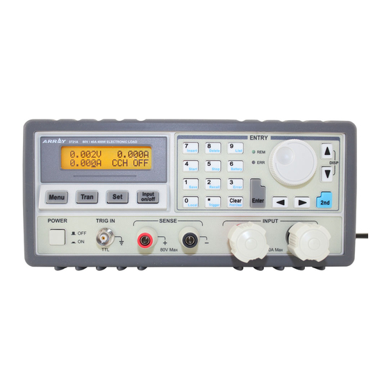
1.2 Front Panel .................................................................................................................................. 2
1.3 Rear Panel ................................................................................................................................... 2
1.4 Keypad Function ........................................................................................................................ 3
1.5 Annunciators ............................................................................................................................... 4
1.6 Menu ............................................................................................................................................ 4
1.6.1 Main Menu ....................................................................................................................... 4
1.6.2 Mode Selection and Parameter Setting Menu ............................................................. 5
1.6.3 Transient Operation Menu ............................................................................................. 6
1.6.4 List Operation Menu ...................................................................................................... 6
1.7 Display Messages ........................................................................................................................ 6
1.8 Remote Programming .................................................................................................................. 9
Chapter2 Functions and Features ........................................................................................................ 10
2.1 Local and Remote Control ...................................................................................................... 10
2.2 Main Functions: ........................................................................................................................ 10
2.3 Basic Test Functions ................................................................................................................. 10
2.3.1 Constant Current Mode ............................................................................................... 11
2.3.1.1 Setting Ranges .................................................................................................... 11
2.3.1.2 Immediate Current Level .................................................................................. 12
2.3.1.3 Triggered Current Level ................................................................................... 12
2.3.1.4 Transient Current Level .................................................................................... 12
2.3.1.5 Software Current Limit ..................................................................................... 12
2.3.2 Constant Voltage Mode (CV) ....................................................................................... 12
2.3.2.1 Setting Ranges .................................................................................................... 13
2.3.2.2 Immediate Voltage Level ................................................................................... 13
2.3.2.3 Triggered Voltage Level ..................................................................................... 13
2.3.2.4 Transient Voltage Level ..................................................................................... 13
2.3.3 Constant Resistance Mode (CR).................................................................................. 13
2.3.3.1 Setting Ranges .................................................................................................... 14
2.3.3.2 Immediate Resistance Level ............................................................................. 14
2.3.3.3 Triggered Resistance Level ............................................................................... 14
2.3.3.4 Transient Resistance Level ................................................................................ 15
2.3.4 Constant Power Mode (CP) ......................................................................................... 15
2.3.4.1 Setting Ranges .................................................................................................... 16
2.3.4.2 Immediate Power Level ..................................................................................... 16
2.3.4.3 Triggered Power Level ....................................................................................... 16
2.4 Transient Operation ................................................................................................................. 17
2.4.1 Continuous Transient Operation ................................................................................. 17
2.4.2 Pulsed Transient Operation ......................................................................................... 18
2.4.3 Toggled Transient Mode ............................................................................................... 20
2.5 List Operation ........................................................................................................................... 21
2.6 Battery Discharge Operation .................................................................................................. 22
2.7 Short Circuit Operation .......................................................................................................... 23
1
Advertisement
Table of Contents

Related Manuals for Array electronic 3720A


Summary of Contents for Array electronic 3720A
-
Page 1: Table Of Contents
Chapter1 General Introduction ......................1 1.1 Function Features ........................1 1.2 Front Panel ..........................2 1.3 Rear Panel ........................... 2 1.4 Keypad Function ........................3 1.5 Annunciators ..........................4 1.6 Menu ............................4 1.6.1 Main Menu ........................4 1.6.2 Mode Selection and Parameter Setting Menu ............. 5 1.6.3 Transient Operation Menu ..................... - Page 2 2.8 Triggered Operation ......................... 23 2.9 Input Control ..........................24 2.9.1 Turning On/Off the Load ..................... 24 2.9.2 Von Point/Von Latch ..................... 25 2.9.3 Current Limit in CV Mode ..................26 2.9.4 Current Rise Rate ......................26 2.9.5 Current Fall Rate ......................26 2.10 Measurement Function ......................
- Page 3 4.8 List Operation ........................49 4.8.1 List Editing ........................50 4.8.2 Modifying, Adding, Inserting, Deleting the List ............52 4.8.3 Starting/Stopping the List .................... 54 4.9 Battery Discharge Operation ....................55 4.10 Saving and Recalling ......................56 4.11 Clearing Protection Settings ....................57 4.12 Error Messages ........................
-
Page 4: Chapter1 General Introduction
ARRAY 372x Series programmable electronic load,as a new generation of product developed by ARRAY Electronic Co., Ltd., is designed with high performance. It provides you powerful test function, user-friendly HMI, as well as RS232, USB, GPIB interfaces to support SCPI and Labview. -
Page 5: Front Panel
1.2 Front Panel Fig. 1-1 Front Panel Function key Power switch External trigger input terminal Remote sense terminal Input binding posts Knob Entry keys/secondary function keys Annuciators Switch key for secondary function Left&Right key Up & Down key/Display-switching key 1.3 Rear Panel Fig1-2 Rear Panel AC input socket Line voltage switch... -
Page 6: Keypad Function
1.4 Keypad Function There are three groups of keypads on the front panel: the Function Keys, the Entry Keys, which composite with secondary functions, and the Direction Keys. The secondary functions of the Entry Keys are printed in blue. To use the secondary function, please press key first, then press the relevant key. -
Page 7: Annunciators
Right key Up key Down key Switch key for secondary function Note: Up and Down key can be used as a switch key for displaying load status and actual power during basic operating modes. 1.5 Annunciators Indicates that the electronic load is in remote status. Indicates that a remote programming error has occurred. -
Page 8: Mode Selection And Parameter Setting Menu
Baud Rate Baud rate setting RS232 Interface 2400 4800 *9600 19200 38400 2400 4800 9600 19200 38400 Parity Check Parity check setting *None Even Odd None Even Odd Data Bit Data bits length *8 7 8bits 7bits Stop Bit Stop bit length *1 2 1bit 2bits Flow Control... -
Page 9: Transient Operation Menu
1.6.3 Transient Operation Menu Press key in desired mode to enable its transient operation, and press key to enter into transient setting menu, which is shown as below: Function Description Example LevelL Transient low level 1.000A LevelH Transient high level 2.000A TimeL Time for transient low level... - Page 10 ① CC Mode: The first line shows measured voltage and current levels. The second line shows current set level, CC mode (CCH indicates constant current high range; CCL indicates constant current low range) and input status of the load: (ON, OFF). ②...
- Page 11 ④ CP Mode: The first line shows measured voltage and current levels. The second line shows power set level, CP mode (CPC indicates constant power-current source mode; CPV indicates constant power-voltage source mode), and input status of the load: (ON, OFF). ⑤...
-
Page 12: Remote Programming
⑧ Short Circuit Operation: The first line shows measured voltage and current levels. The second line shows set level in short circuit (Take 3721A as an example, short circuit test current in CCL is 4.4A; short circuit test current in CCH is 44A; short circuit test voltage in CV is 0V; short circuit test resistance in CRL is 0.018Ω;... -
Page 13: Chapter2 Functions And Features
Chapter2 Functions and Features The functions and features of electronic load will be described in this chapter, which helps you to know ARRAY 372x Series better. 2.1 Local and Remote Control ARRAY 372x Series electronic load can be controlled via the keypad and knobs in the front panel, or by remote controller via remote interface. -
Page 14: Constant Current Mode
The CC mode and parameters can also be set via remote command (MODE CCL, MODE CCH, CURRent <NRf+>). Fig.2-1 CC Mode 2.3.1.1 Setting Ranges The setting ranges for different models of load are listed as follows: Model 3720A 3721A 3722A 3723A 3724A 0~3A... -
Page 15: Immediate Current Level
2.3.1.2 Immediate Current Level The immediate current level refers to the current set value in CC mode, which can be programmed via mode selection and parameter setting menu, or via remote command (CRRRent <NRf+>). The immediate current level can also be modified directly with left/right keys ( and the knob. -
Page 16: Setting Ranges
Fig.2-2 CV Mode 2.3.2.1 Setting Ranges The voltage setting ranges for different models of load are listed as follows: Model 3720A 3721A 3722A 3723A 3724A Voltage 0~80V 0~80V 0~200V 0~200V 0~500V 2.3.2.2 Immediate Voltage Level The immediate voltage level refers to the voltage set value in CV mode, which can be set via mode selection and parameter setting menu, or via remote command (VOLTage <NRf+>). -
Page 17: Setting Ranges
(MODE CRL, MODE CRM, MODE CRH, RESistance <NRf+>). Fig.2-3 CR Mode 2.3.3.1 Setting Ranges The setting ranges for different models of load are listed as follows: Model 3720A 3721A 3722A 3723A 3724A 0.02~2Ω... -
Page 18: Transient Resistance Level
level will have no effect on the input until the CR mode becomes active. The triggered resistance level only can be set via remote command (RESistance:TRIGgered <NRf+>). Once a resistance level is triggered, subsequent triggers will become invalid until another (RESistance:TRIGgered <NRf+>) command is received. -
Page 19: Setting Ranges
2.3.4.1 Setting Ranges The setting ranges for different models of load are listed as follows: Model 3720A 3721A 3722A 3723A 3724A... -
Page 20: Transient Operation
2.4 Transient Operation When the transient operation is enabled, the load periodically switch between two levels (LevelH and LevelL), which can be applied to test the dynamic characteristics of the power supply. The transient operation can be executed in the CC, CV and CR modes, and has three operating statuses: Continuous, Pulsed, and Toggled. -
Page 21: Pulsed Transient Operation
Then press key to turn on the input; Or via remote command to set: SCPI Command Description TRAN ON Enables transient operation CURR:LOW 5 Sets transient current low level to 5A CURR:HLGH 10 Sets transient current high level to 10A TRAN:LTIM 500us Sets transient low level time to 500us TRAN:HTIM 500us... - Page 22 command (*TRG/. TRIGger). The trigger becomes effective only when the load remains at transient low level. Each trigger leads to one pulse. In the duration of rising edge, transient high level, and falling edge, any trigger will be ignored. For example: assume that the CCH range is active, and the input is in OFF status, then the transient parameters should be set as follows: Press key to enter into transient operation;...
-
Page 23: Toggled Transient Mode
Fig. 2-7 Pulsed Transient Operation 2.4.3 Toggled Transient Mode The trigger function is required for toggled transient operation. When there is no trigger occurs, the load remains at a transient level. After a trigger has been received, a toggle operation will be executed, and another transient level will be reached after the duration of rising edge or falling edge. -
Page 24: List Operation
CURR:LOW 5 Sets transient current low level to 5A CURR:HIGH 10 Sets transient current high level to 10A TRAN:RTIM 100us Sets the time for transient rising edge to 100us TRAN:FTIM 200us Sets the time for transient falling edge to 200us TRAN:MODE TOGG Selects toggled operating mode INPUT ON... -
Page 25: Battery Discharge Operation
The load can real-time display battery voltage, discharge current, discharge time, and discharge capacity during the test. The maximum battery discharge time is 99hours 99minutes 99 seconds, and the maximum battery capacity for different models is listed as follows: Model 3720A 3721A 3722A 3723A... -
Page 26: Short Circuit Operation
(INPut:SHORt ON/OFF). The other set values will not be changed when the short circuit operation is enabled. The short-circuit value depends on the present operating mode of the load, and the short-circuit value for each model is shown as follows: Model 3720A 3721A 3722A 3723A 3724A 3.3A... -
Page 27: Input Control
Triggering a preset level Transfer all pending preset levels to the immediate levels. For the presently active mode, the new level will appear at the input at once if the input is turned on. For the modes which are not presently active, the preset levels will not take effect at the input until the corresponding mode becomes active. -
Page 28: Von Point/Von Latch
2.9.2 Von Point/Von Latch When the external input voltage is less than the Von Point, the load will not be enabled even though the input has been turned on. The load will be enabled till the external input voltage reaches or exceeds the Von Point. -
Page 29: Current Limit In Cv Mode
2.9.3 Current Limit in CV Mode The CV Curr Limit is used to limit the maximum input current in CV mode. If the voltage is still larger than the set level while the current limit has been reached, the load will switch to the CC mode. Please see figure 2-13. -
Page 30: Measurement Function
Fig.2-15 Current Fall Rate Note: The Curr Fall Rate can be effective only in CCH and CCL mode, and the actual rise rate is one tenth of the set level in CCL. 2.10 Measurement Function The electronic load has measurement system with high resolution. The input current level and voltage level can be measured in real time. -
Page 31: Reading Remote Programming Errors
CV current limit Current limit in CV mode Voltage Hlevel Transient high voltage level Voltage Llevel Transient voltage low level Resistance level Immediate resistance level 2000Ω Resistance Hlevel Transient high resistance 2000Ω high level Resistance Llevel Transient resistance low 2000Ω level Power level Immediate power level... -
Page 32: Status Report
Remote programming errors can be checked by pressing key after pressing key on the front panel. The remote command (SYSTem:ERRor?) can reads back the error codes and error messages when it is in remote control. All errors are saved in one error queue. The errors in this error queue are read in the order in which they occurred. -
Page 33: Overvoltage
2.14.2 Overvoltage The overvoltage protection level is set at a predetermined voltage, which cannot be changed by the user. When the input voltage exceeds this predetermined voltage, the overvoltage protection will be enabled, and the input is turned off with OV displayed, meanwhile, the OV and VF status register bits are set, and will remain set until they are reset and overvoltage condition is removed. -
Page 34: Knob Function
trigger transient operation, and selecting List is used to trigger sequence (list) operation. 2.15.2 Knob Function The Knob in main menu is used to enable/disable the knob function. Select On to enable the knob function, and select Off to disable. 2.15.3 Key Sound The Key Sound in main menu is used to control the key sound. -
Page 35: Connections On The Rear Panel
System ADC test failed Rundown too noisy Keypad self-test error EEPROM checksum failed Temperature test failed If there is no error is detected, the LCD will show CCH, the initial display, and the input will be turned off. If the parameters was modified previously and saved in location 0, the load will recall these modified parameters automatically. -
Page 36: Connections On The Front Panel
Not used Not used Not used The interface parameters can be set in the MENU, and you can use SCPI language for programming to realize the communication with the load. GPIB Interface: The load provides a GPIB interface, and you can set its address to any value between 0 and 30 in MENU. -
Page 37: Wiring
The external trigger input terminal on the front panel is a BNC connector, in which the middle part is the input+, and the outer casing is the input-. It receives 5V TTL-compatible falling-edge trigger signals. In order to get a reliabale trigger, the duration time of low level should be longer than 10us. -
Page 38: Chapter 4 Local Operation
Chapter 4 Local Operation The local operation of the load has been briefly introduced in Chapter 2. In this chapter, it will be explained in details with examples. 4.1 Local Control If it is needed to control the load from the front panel, the load must stay in the local control status. -
Page 39: Turning The Input On/Off
protection status of the load will become effective. In this case, disconnect the power supply from the load and then make the correct connections. After the power supply is correctly connected to the load, press key + key to clear the RV protection status or restart the load. - Page 40 0.000V 0.000A key to check the current power 5.120A 0.000W value. For the above operating procedures, the corresponding SCPI commands should be: MODE ;Sets the mode CURR ;Sets the current value ;Turns on the load Example 2: Current setting is 5.8A in CCH, input is on. Solution 1: Procedures Operation Descriptions...
-
Page 41: Cv Mode
MODE ;Sets the mode CURR ;Sets the current value ;Turns on the load Note: In CCH status or CCL status, CCH /CCL will be shown respectively in the lower right corner of the display. 4.5.2 CV Mode Example 1: Take 3721A as an example, set the load to CV mode and the voltage value to 50V in CCH. -
Page 42: Cr Mode
keys to input the voltage value to 60. 0.000V 0.000A Press key to confirm and exit the mode 60.000V CV OFF selection and parameter setting menu. 0.000V 0.000A Press key to turn on the load. 60.000V CV ON Solution 2: Procedures Operation Descriptions Display... - Page 43 selection and parameter setting menu. 0.000V 0.000A Press key to turn on the load. 1.5000Ω CRL ON 0.000V 0.000A Check the present power value with 1.5000Ω 0.000W For the above operating procedures, the corresponding SCPI commands should be: MODE ;Sets the mode ;Sets the resistance value ;Turns on the load Example 2: Set the resistance value to 1.8Ωin CRL.
-
Page 44: Cp Mode
the load is in CRH status, CRM status or CCL status. 4.5.4 CP Mode CP Mode includes constant power-current source mode (CPV) and constant power-voltage source mode (CPC). Example 1: Take 3721A as an example, set the load to CPV and set the power value to 100W in CRL. -
Page 45: Short Circuit Operation
0.000V 0.000A Press key to turn on the load. 200.00W CPV ON Solution 2: Procedures Operation Descriptions Display 0.000V 0.000A Move the cursor to the hundredths with key. 100.00W CPV OFF Rotate the knob to set the hundredths to 2. 0.000V 0.000A (Rotating the knob will change the set value... -
Page 46: Transient Operation
(short circuit) item with key. Short: key or knob to set On, and press key to *On Off confirm. 0.000V 0.000A Press key to exit the main menu. The display shows “s” 0.000V sCV OFF to indicate in CV mode. 0.000V 0.000A Press key to enter into the mode selection and parameter... -
Page 47: Continuous Transient Operation
1. Press key to enter into the mode selection and parameter setting menu; use keys to select one basic operating mode; press key to confirm and exit the mode selection and parameter setting menu. Press key to enter into transient operation. The display shows “t” to indicate in the basic test mode. - Page 48 LevelL:1.000V Use Entry keys or use the knob together with keys LevelH:80.000V ► to set LevelL to 1, and press key to confirm. TimeL :530.00ms ► Use Entry keys or use the knob together with keys TimeH :500.00ms to set LevelH to 5, and press key to confirm.
-
Page 49: Pulsed Transient Operation
TRAN:RTIME 10ms ;Sets a value to time for rising edge TRAN:FTIMR 20ms ;Sets a value to time for falling edge TRAN:MODE CONT ;Selects continuous transient operation ;Turns on the load 4.7.2 Pulsed Transient Operation Example 1: Assume that the load is in external triggering mode, set the load current value to periodically switch between 1A and 5A;... -
Page 50: Toggled Transient Operation
to set TimeF to 10ms, and press key to confirm. Mode: Puls ► ◄ ► keys or knob to set Mode value to pulse, and press key to confirm. 0.000V 0.000A Press key to exit the transient operation menu. 1.000A CCH OFF 0.000V 0.000A Press... - Page 51 LevelL:2000.0Ω ► Press key to enter into the transient operation menu.. LevelH:2000.0Ω LevelL:200.00Ω Use Entry keys or use the knob together with keys LevelH:2000.0Ω ► to set LevelL to 200, and press key to confirm. TimeL:400.00ms ► Use Entry keys or use the knob together with keys TimeH:200.00ms to set LevelH to 500, and press...
-
Page 52: List Operation
4.8 List Operation The operating procedures for sequence operation are shown below: Press key + key to enter into list operation menu. Use Entry keys or the knob to select list number (No.), and press key to confirm. key to select list memo (Memo). Use knob and keys to edit memo (max. -
Page 53: List Editing
operating procedure 9. 13. If it is needed to delete an edited step, use keys to select this step. The LCD display will stop flashing, and press key + key to delete. If there is only one step exists, it will exit the step edit screen. Press key to exit step edit screen, and save the sequence data in EEPROM assigned by the sequence number. - Page 54 No.: ► Press key + key to enter into sequence operation Memo: menu. Use Entry keys or the knob to set the sequence number (No.) to No.: ► Memo: 0, and press key to confirm (recall the sequence in EEPROM assigned by the sequence number). No.: key to select sequence memo (Memo).
-
Page 55: Modifying, Adding, Inserting, Deleting The List
The five sequence steps have been edited, and there is no need 0.00000s 20.000Ω to edit the step6. Press key to exit step edit screen and save the sequence data in EEPROM assigned by the sequence number. Data:<New/Edit> key to select “Count”; use Entry keys or the knob Count: ►... - Page 56 menu. Step2 Data:<New/Edit> ► key to select Data:<New/Edit>. Count: Step3 1.00000s key or knob to select Edit, and press key to 1.0000A confirm and enter step edit screen. Step4 1.00000s key to select time parameter, and the time set value 1.0000A flashes.
-
Page 57: Starting/Stopping The List
Step16 Chain: Off ► key to select Chain. Step17 Use Entry keys or the knob to input 0 (it is chained to itself to Chain: 0 ► realize continuous execution). Press key to confirm and save the Chain value in EEPROM assigned by the sequence number. -
Page 58: Battery Discharge Operation
4.9 Battery Discharge Operation Battery discharge operation diagram: The operating procedures for battery discharge operation are shown below: 1. Press key to turn off the load, and connect the tested battery correctly. 2. Press key + key to enter into battery discharge operation screen. Press key to enter into battery discharge parameters edit screen. -
Page 59: Saving And Recalling
screen. Use Entry keys or the knob together with keys to input termination voltage to 15V. Press key to confirm. Step4 MinVolt:15.000V Use Entry keys or the knob together with keys to input DisCurr:3.000A ► discharge current to 3A. Press key to confirm. -
Page 60: Clearing Protection Settings
power-on settings. Procedures Operation Descriptions Display Set the mode to CCL; set the current value to 2A; turn on the load ( 0.000V 0.000A please refer to 4.5.1 for detailed operations). 2.0000A CCL ON Save File Press key + key to enter into the saving menu. Press Entry keys or the knob to select the Location 0 for saving. -
Page 61: Error Messages
0.000V 0.0000A Press key + key. 2.0000A CCL OFF For the above operating procedures, the corresponding SCPI commands should be: INP:PROT:CLE ;Clears the protection status 4.12 Error Messages When an error occurs to the load, the operating procedures are shown below: Press key + key to display the error messages. -
Page 62: Main Menu
TRIG:FUNC LIST ;Selects “LIST” for trigger function "INIT" ;Initialize the trigger TRIG ;A trigger occurs 4.14 Main Menu The operating procedures for the main menu are shown below: Press key to enter into the main menu. keys to select the menu item. Use the knob or keys to select the parameter;... -
Page 63: Von Point/Von Latch
setting menu; use keys to select CV mode. Press key to confirm and exit the mode selection and parameter setting menu. 0.000V 0.000A Press key to turn on the load. 0.000V sCV ON For the above operating procedures, the corresponding SCPI commands should be: INP:SHORT ON ;Sets the load to short circuit MODE... -
Page 64: Current Rise/Fall Rate In Cc Mode
see 4.5.2 section for detailed operations) 2.000V CV OFF Step2 Load Default: Press key to enter into the main menu. Yes *No Step3 CV Curr Limit: key to select the menu item “CV Curr Limit”; use Entry 20.000A keys or the knob together with keys to input the current limit value to 20A. -
Page 65: Trigger Function Selection
0.000V 0.000A Press key to turn off the load. 2.000A CCH OFF For the above operating procedures, the corresponding SCPI commands should be: MODE ;Sets the mode CURR ;Sets the current value to 2A CURR:RISE:RATE 0.002 ;Sets the current rise rate in CC mode to 0.002A/us CURR:FALL:RATE 0.005 ;Sets the current fall rate in CC mode to 0.005A/us... -
Page 66: Communication Interface
key to select the parameter “On”. Press key to confirm. 0.000V 0.000A Press key to exit the main menu. 0.000A CCH OFF 4.14.9 Communication Interface Example 1: Select RS232 interface; set the baut rate to 9600; set parity check to None; set data bit to 8;... -
Page 67: Chapter5 Remote Programming Operation
Steps Operation Descriptions Display Step1 Load Default: Press key to enter into the main menu. Yes *No Step2 Interface: key to select the menu item “Interface”; use the knob or RS232 USB *GPIB key to select the parameter “GPIB”. Press key to confirm. -
Page 68: Gpib
5.1.3 GPIB GPIB is optional. It can be used only when the load has installed GPIB communication module and the relevant driver has installed on the computer. Use GPIB cable to connect the load to a computer correctly. Select the GPIB interface in the MENU, and set GPIB address. Each instrument you connect to the GPIB interface has a unique address assigned to it. -
Page 69: Transient Levels
The CC, CR, CV, and CP values can be programmed whether or not the associated mode is active. If the input is turned on, all of the applicable values will take effect at the input when the associated mode is selected. 5.6.2 Transient Levels The transient CC, CV, or CR level must be set to a higher level than the respective low level, or the transient operation will be disabled. -
Page 70: Pulsed Transient Operation Example
13 "*TRG" ;*TRG command generates a 1millisecond high-level pulse at the load`s input Specifications (The warm-up time is 30 minutes. Specifications indicate warranted performance in the 25°C ± 5°C region of the total temperature range.) 3720A 3721A Model Input Ratings... - Page 71 Current 0~30A 0~40A Voltage 0~80V 0~80V 250W at 40ºC 400W at 40ºC Power Input Characteristics Input Characteristics Minimum Operation Voltage 0.6V 0.6V @ Full Scale Current Constant Current Mode Low Range 0~3A 0~4A Resolution 0.1mA 0.1mA Accuracy 0.1%+5mA 0.1%+5mA High Range 0~30A 0~40A Resolution...
- Page 72 Range 0~250W 0~400W Resolution @P<100W @P≥100W 10mW 10mW Accuracy 0.2%+600mW 0.2%+600mW Current Measurement Low Range 0~3A 0~4A Resolution 0.1mA 0.1mA Accuracy 0.05%+4mA 0.05%+4mA High Range 0~30A 0~40A Resolution Accuracy 0.05%+8mA 0.05%+8mA Voltage Measurement Range 0~80V 0~80V Resolution Accuracy 0.1%+8mV 0.1%+8mV Power Measurement Range 0~250W...
- Page 73 Step Time 10us~100000s 10us~100000s Resolution 10us 10us Accuracy 0.2%+10us 0.2%+10us Number of Steps 1~50 1~50 Cycle 1~65535 1~65535 Store Capacity 7 lists 7 lists Expanded Functions Chain Chain Battery Discharge Discharge Time 1s~100h 1s~100h Resolution Accuracy 0.2%+1s 0.2%+1s Battery Capacity 1mAh~3000Ah 1mAh~4000Ah Resolution...
- Page 74 Environmental Conditions Temperature 0~50ºC 0~50ºC Relative Humidity ≤85% ≤85% RS232, GPIB, USB RS232, GPIB, USB Remote Interface SCPI SCPI Programming Language AC Input Voltage AC110V or AC220V±15% AC110V or AC220V±15% Frequency 48 to 63Hz 48 to 63Hz 5.8kg 5.8kg Net Weight 3722A 3723A Model...
- Page 75 Low Range 0.0666~6.66Ω 0.0666~6.66Ω Resolution 0.1mΩ 0.1mΩ Accuracy @I>3A 0.5%+40mΩ 0.5%+40mΩ Middle Range 6.66~666Ω 6.66~666Ω Resolution 2.6uS 2.6uS Accuracy @V>20V 0.3%+375uS 0.3%+375uS High Range 66.6~6660Ω 66.6~6660Ω Resolution 0.29uS 0.29uS Accuracy @V>20V 0.3%+188uS 0.3%+188uS Constant Power Mode Range 0~200W 0~350W Resolution @P<100W @P≥100W 10mW 10mW...
- Page 76 Frequency Range 0.38Hz~50kHz 0.38Hz~50kHz High/Low Time 0~655.35ms 0~655.35ms Resolution 10us 10us Accuracy 0.2%+10us 0.2%+10us Rising/Falling Time 10us~655.35ms 10us~655.35ms Resolution 10us 10us Accuracy 0.2%+10us 0.2%+10us List Characteristics Step Time 10us~100000s 10us~100000s Resolution 10us 10us Accuracy 0.2%+10us 0.2%+10us Number of Steps 1~50 1~50 Cycle 1~65535...
- Page 77 Maximum DC Input Current Voltage 210V 210V OV, OC,OP, OT, RV OV, OC,OP, OT, RV Protection Features Reverse Current Capacity Input OFF Input ON Ripple and Noise Current(rms/p-p) 3mA/30mA 3mA/30mA Voltage(rms) Environmental Conditions Temperature 0~50ºC 0~50ºC Relative Humidity ≤85% ≤85% RS232, GPIB, USB RS232, GPIB, USB Remote Interface...
- Page 78 0~20A High Range Resolution 0.1%+10mA Accuracy Constant Voltage Mode Range 0~500V Resolution Accuracy 0.1%+62.5mV Constant Resistance Mode Low Range 0.125~12.5Ω Resolution 0.1mΩ Accuracy @I>2A 0.5%+150mΩ 12.5~1250Ω Middle Range 13.8uS Resolution 0.3%+1mS Accuracy@V>50V High Range 125~12500Ω Resolution 1.54uS Accuracy@V>50V 0.3%+0.5mS Constant Power Mode Range 0~250W Resolution@P<100W...
- Page 79 Accuracy 3% + 10us Transient Operation Transient Mode Continuous, Pulse, Toggled Frequency Range 0.38Hz~50kHz High/Low Time 0~655.35ms Resolution 10us Accuracy 0.2%+10us Rising/Falling Time 10us~655.35ms Resolution 10us Accuracy 0.2%+10us List Operation Step Time 10us~100000s Resolution 10us Accuracy 0.2%+10us Number of Steps 1~50 Cycle 1~65535...
- Page 80 Current Voltage 525V OC, OV, OT, OP, RV Protection Features Reverse Current Capacity Input OFF Input ON Ripple and Noise Current(rms/p-p) 3mA/30mA Voltage(rms) 30mV Environmental Conditions Temperature 0~50ºC Relative Humidity ≤85% RS232, GPIB, USB Remote Interface SCPI Programming Language AC Input Voltage AC110V or AC220V±15% Frequency...
Need help?
Do you have a question about the 3720A and is the answer not in the manual?
Questions and answers