Table of Contents
Advertisement
Butternut
80/40/30/20/15/17/12/10/6 Meters
Nine-Band
Vertical Antenna
© Butternut 2021
1200 Southeast Ave. - Tallmadge, OH 44278 USA
Phone: (800) 777-0703 ∙ Fax: (330) 572-3279
Tech Support and International: (330) 572-3200
HF9V
®
BUT-HF9V
BUT-HF9V-INS-Revision 5
Artists rendition
of an installation
Advertisement
Table of Contents

Related Manuals for Butternut HF9V


Summary of Contents for Butternut HF9V
- Page 1 Butternut HF9V ® 80/40/30/20/15/17/12/10/6 Meters Nine-Band Vertical Antenna BUT-HF9V BUT-HF9V-INS-Revision 5 © Butternut 2021 Artists rendition 1200 Southeast Ave. - Tallmadge, OH 44278 USA of an installation Phone: (800) 777-0703 ∙ Fax: (330) 572-3279 Tech Support and International: (330) 572-3200...
-
Page 2: Overhead Power Line Safety
® The classic Butternut HF9V Nine-band vertical antenna operates on 75/80, 40, 30, 20, 17, 12, 15, 10 and 6 meters. Designed with corrosion-resistant aluminum tubing, 26 feet tall and only a 2.2 ft wind load, this antenna is very durable and attractive. -
Page 3: Theory Of Operation
Theory of Operation The first L/C circuit generates enough reactance to bring the whole HF9V to resonance on 80 meters allowing it to act as an electrical 1/4-wavelength radiator. It also generates enough capacitive reactance to produce another discrete resonance at about 11 MHz. -
Page 4: Tools Required
Information on guying the ® ® Butternut HF9V is included in this manual. Information on guying the Butternut HF9V can be found in the section “Guying the HF9V Antenna”. BUT-GRK Ground Radial Kit for ground mounting - 80 through 6 meter operation... -
Page 5: Site Selection
Site Selection Ideally, select a mounting location clear from power lines, structures and other antennas by a minimum of 45 feet. Consider overhead power lines, utility cables and wires. The vertical should be mounted away from local noise sources or other metallic objects which can re-radiate noise and affect the tuning, radiation pattern and SWR. -
Page 6: Radial System
But, installing many more radials helps overcome unknown poor soil conditions, improves efficiency and ensures the best performance possible from this Butternut vertical antenna. Radial Wire that is 14 gauge stranded copper with black relaxed PVC insulation wire is suggested for longevity. DXE- RADW-32RT or 65RT Radial Wire Kits are available. -
Page 7: Aluminum Tubing Information
Q mounted on tube (A) of the HF9V or mounted on the antenna base if the optional BUT-MPS Mounting Post Sleeve is used. In either case, a ground wire attachment from the lower tube (A) to the Radial Plate should be made to ensure a good RF connection. - Page 8 5. When assembling the aluminum tubing sections, ensure the area is clear of grass, dirt or other foreign material that could cause problems during assembly of the closely fitted telescoping sections. Assembly Note: For reference, a completed HF9V Antenna is shown at the end of this manual following the detailed parts list. ™ Note: Jet-Lube SS-30 Anti-Oxidant should be used between all antenna element sections.
- Page 9 1. Check to be sure that no parts are missing (see assembled antenna pictorial page) 2. If the antenna is to be installed at ground level, install mounting tube (A) in a hole approximately 21 inches deep so the lower end of the fiber rod insulator is approximately 2-3 inches or less above ground level.
- Page 10 4. From the center of the insulator, measure downward to a point that is 13” along tube (B) and make a pencil mark. 5. From the center of the insulator, measure upward to a point that is 9-3/8" along tube (B1) and make a pencil mark.
- Page 11 9. Stretch the 80 meter (larger) coil on the coil assembly 80/40 meter (C) until the bottom of the lower clamp is even with the lower mark. Secure with a #10 flat washer, lock washer and wing nut. 10. Locate the capacitor assembly 80/40 meter (D) and install capacitor bracket 80 meter (D1) on the larger 200 pF capacitor using the installed screw.
- Page 12 15. Insert the end of tube (E) into tube (B1) and secure with a # 8 x 1-1/2" screw, lock washer and hex nut. 16. Locate coil support tube 30 meter (O) and measure to a point 9-7/8” down from the end of the plastic insulator.
- Page 13 22. Slide the remaining clamp from the above assembly over tube (E) and position it so the coil support tube L bracket (O1) is even with fourth turn, counting from the top of the 40 meter coil on the coil assembly 80/40 meter (C) and tighten the hex nut.
- Page 14 Steps 31 through 48 are for installing the 15 and 6 meter parts to the antenna. Use the following diagram to assist in identifying the parts and their proper locations. On tubes E, F and G, the hole that is drilled 5/8” from the end goes toward the top of the antenna. 31.
- Page 15 36. Insert the end of tube (H) into the end of tube (G) and secure with a # 8 x 1" screw, lock washer and hex nut. 37. Position wire clamp 0.625" 6M with wire (T) around tube (H) so the top edge is 33-1/4” from the upper end of the tube.
- Page 16 42. Locate the 15M wire clamp 0.625" with insulator (M) and position it around tube (H). Final tightening and positioning will be done in a later step. 43. Insert the end of tube (I) into the end of tube (H) and secure with a # 8 x 1" screw, lock washer and hex nut.
- Page 17 48. Line up wire clamp 0.875" 15M with insulator (K), wire clamp 0.750" 15M with insulator (N) and wire clamp 0.625" 15M with insulator (M) with wire clamp 0.500" 15M with wire (L) and tighten all clamps making sure the wire is moderately taut but not enough to cause the upper tubing section to bow.
- Page 18 53. Install the Red Coil (Q) and the Feedpoint Connector (R1) in place as shown below. The Red Coil and the Feedpoint Connector span over the insulator between Tube (A) and Tube (B). The Red lead on the Feedpoint Connector connects to Tube (B), the Black lead on the Feedpoint Connector connects to Tube (A).
- Page 19 Checkout and Adjustment Adjustments will have to be made before trying to transmit with this antenna system. Installations vary considerably and there are no ‘set’ measurements that will work for all the variables in the installation. The dimensions and coil settings that were used during assembly are somewhat close and may produce reasonably low VSWR readings over the entire 10, 15, 20 and 30 meter bands and at least 250 kHz of the 40 meter band.
- Page 20 0.500" 15M with wire (L) and wire clamp 0.875" 15M with insulator (K). A change of 2 inches will shift the VSWR curve approximately 300 kHz. Check VSWR on 6 meters. To raise the frequency of the lowest VSWR, shorten the length of the wire and to lower frequency increase the wire length.
- Page 21 6. Check VSWR on 20 meters. Tuning is quite broad on this band because the antenna is physically much taller than a 1/4-wavelength. To raise the frequency of the lowest VSWR, reposition the 30 meter assembly so that the coil support tube 30 meter L bracket (O1) can be replaced on the next lower turn of the 40 meter coil.
-
Page 22: Lightning Protection
Transmitters having so-called broadband solid-state output circuits (no tuning or loading controls) may be especially troublesome in this regard, whereas the older vacuum tube pi-network transmitters can usually be adjusted for maximum output over a tuning range where the VSWR does not exceed 2.5:l. - Page 23 Adjust coils carefully! Remember, tuning, is sharp on these bands, so it is easy to pass the resonant point, then assume erroneously that the antenna isn't tuning. BEFORE you call Butternut for help, please double check your installation, including all connections and dimensions. Tune carefully and systematically. Have SWR curves available.
- Page 24 A Few Words About the Capacitors. The door-knob capacitor used on the Butternut Verticals can be difficult to find. Over the years the shape and size has changed depending on the source of the capacitors. Prior to October of 2016 - the following capacitor assemblies were used:...
- Page 25 Guying the HF9V Antenna The HF9V is designed to survive winds of up to 80 mph without guying in the absence of ice loading or heavy precipitation, but over a period of time it is to be expected that frequent or even constant flexing or vibration will reduce the chances for survival in winds that would not damage a newly installed antenna.
- Page 26 ® Butternut HF9V Parts List Description Description Tube A with Insulator, 1-1/8” dia x 24” long Wire Clamp, 5/8” with Wire - 6M Tube B element, 1-1/8” dia x 48” long Wire Clamp, 3/4” with Insulator - 6M Tube B1 with Insulator, 1-1/8” dia x 12” long Wire Clamp, 7/8”...
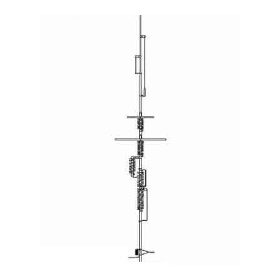
- Page 27 HF9V Assembly with Enlarged Details [Dimension in inches. Drawings not to scale.] - 30 - - 26 -...
-
Page 28: Technical Support
Buyer or acquired from others at Buyer’s specifications. In addition, Butternut’s warranties do not extend to other equipment and parts manufactured by others except to the extent of the original manufacturer’s warranty to Butternut...
Need help?
Do you have a question about the HF9V and is the answer not in the manual?
Questions and answers