Table of Contents
Advertisement
Quick Links
WARNING: DO NOT INSTALL THE ANTENNA WHERE ANY PART
OF IT CAN COME INTO CONTACT WITH POWER LINES IN THE
EVENT OF STRUCTURAL FAILURE, DURING INSTALLATION OR
IN THE COURSE OF NORMAL FLEXING AFTER INSTALLATION
FOR SUCH CONTACT CAN RESULT IN DAMAGE TO PROPERTY,
BODILY INJURY OR EVEN DEATH!
WARNING: IN NO CASE SHOULD THE ANTENNA BE INSTALLED
WHERE STRUCTURAL FAILURE OF ANY PART OF THE
ANTENNA OR ITS SUPPORTING SYSTEM CAN ENDANGER
PERSONS OR PROPERTY.
CAUTION! A GROUNDED ANTENNA WILL BE AT D.C. GROUND
POTENTIAL! TO AVOID THE DANGER OF SHOCK CONNECT ALL
STATION EQUIPMENT TO A GOOD EARTH GROUND. IT IS ALSO
RECOMMENDED THAT ALL STATION EQUIPMENT BE
DISCONNECTED FROM THE POWER MAINS BEFORE
CONNECTING THE FEEDLINE TO THE ANTENNA. PLEASE
CONSULT THE A.R.R.L HANDBOOK OR OTHER REFERENCE
MANUALS FOR ADDITIONAL SAFETY PROCEDURES WHEN
WORKING WITH ELECTRICAL EQUIPMENT.
NOTE: PLEASE READ ALL INSTRUCTIONS THOROUGHLY BEFORE
PROCEEDING TO ASSEMBLY.
NOTE: HIGH PERFORMANCE BUTTERNUT VERTICAL ANTENNAS
REQUIRE A RADIAL SYSTEM FOR ALL INSTALLATIONS.
Butternut offers three systems for installing vertical antennas:
Model GRK Ground Radial Kit for ground mounting—160 thru 6 meter operation
Model RMK-II Roof Mounting Kit for roof mounting—80 thru 6 meter operation
Model CPK Capacitive Counterpoise Kit for compact installations below 25 ft
(7.6 m) above the earth—80 thru 6 meter operation
Please refer to TECH NOTES—GROUND/RADIAL SYSTEMS, at the end of this
instruction, for other mounting schemes and assistance in designing your own
radial system.
831 N Central Ave Wood Dale IL 60191-1219 Tel: 630.238.1183 Fax: 630.238.1186 e-mail: bencher@bencher.com http://www.bencher.com
-1-
Instructions
Model HF9V
00408IZV 100700
Advertisement
Table of Contents

Related Manuals for Butternut HF9V


Summary of Contents for Butternut HF9V
- Page 1 NOTE: HIGH PERFORMANCE BUTTERNUT VERTICAL ANTENNAS REQUIRE A RADIAL SYSTEM FOR ALL INSTALLATIONS. Butternut offers three systems for installing vertical antennas: Model GRK Ground Radial Kit for ground mounting—160 thru 6 meter operation Model RMK-II Roof Mounting Kit for roof mounting—80 thru 6 meter operation Model CPK Capacitive Counterpoise Kit for compact installations below 25 ft (7.6 m) above the earth—80 thru 6 meter operation...
-
Page 2: Required Tools
REQUIRED TOOLS Flat blade screwdriver and pliers. A 1/4", 11/32" and 3/8" nut driver will be helpful. ASSEMBLY Refer to the appropriate diagrams and proceed as follows: 1. Check to be sure that all parts are present. 2. Install tube w/insulator (A) per instructions packaged with mounting system or Tech Notes Ground/Radial Systems. - Page 3 ASSEMBLY NOTE: The outer tab of this clamp may be bent back slightly to provide clearance for the bolt, bending it back into place after assembly. 8. Stretch the 40 meter (smaller) coil on the coil assembly 80/40 meter (C) until the top of the upper clamp is even with the upper mark.
- Page 4 ASSEMBLY coil/capacitor assembly 30 meter (P). 19. Place a #10 washer, lock washer and hex nut on both upper clamps of coil/capacitor assembly 30 meter (P). 20. Pass the lower single clamp of coil/capacitor assembly 30 meter (P) over the insulator end of coil support tube 30 meter (O) and slide the coil downward along the tube until the upper edge of the upper clamp is flush with the end of the insulator.
- Page 5 ASSEMBLY 30. Tighten the hex nut and stretch the coil so that the distance between the upper edge of the lower clamp and the lower edge of the upper clamp is 8 3/4 in (22.2 cm). 31. Position wire clamp 0.875" 15 M w/insulator (K) around tube (F) and use a # 8 x 1"...
- Page 6 ASSEMBLY 45. Measure from the rivet of wire clamp 0.500" 15 M w/wire (L) to a point 11 ft 3 in (3.4 m) along the stranded wire and mark this point. 46. Pass the free end of the stranded wire from wire clamp 0.500" 15 M w/wire (L) through the small holes in wire clamp 0.625"...
- Page 7 ASSEMBLY 53. Install coax 75 ohm matching (R) as shown placing the lug from the center conductor over the screw on tube (B) and the braid over the screw on tube w/insulator (A). 54. Place # 8 washers over each screw and install coil (Q) base matching. Secure with washers, lock washers and hex nuts.
- Page 8 CHECKOUT AND ADJUSTMENT For adjustment purposes a simple VSWR indicator may be used. More accurate measurements may be made at the antenna (i.e., at the junction of the coax 75 ohm matching (R) and the main transmission line) than at the input end of the line, but the tuning conditions that exist at the transmitter will usually be of greater interest in that one's principal concern will be to couple power from the transmitter into the transmission line.
- Page 9 CHECKOUT AND ADJUSTMENT 4. Check VSWR on 20 meters. Tuning is quite broad on this band because the antenna is physically much taller than a quarter wavelength. To raise the frequency of the lowest VSWR, reposition the 30 meter assembly so that the coil support tube 30 meter L bracket (O1) can be replaced on the next lower turn of the 40 meter coil.
- Page 10 CHECKOUT AND ADJUSTMENT 10. Check VSWR on 6 meters. To raise the frequency of the lowest VSWR, shorten the length of the wire and to lower frequency increase the wire length. Alternatively, the upper clamp and the entire 6 meter assembly may be placed higher on the antenna to lower frequency or lower to raise it.
-
Page 11: Theory Of Operation
1/4 stub decoupler providing practically lossless isolation of the upper half of the antenna on that band. On 10 meters the HF9V becomes a 3/4 radiator with considerably greater radiation resistance and efficiency than 1/4 trapped types. On 17 and 12 meters the coils act as packets of reactance which... - Page 12 GUYING The HF9V is designed to survive winds of up to 80 mph (129 kph) without guying in the absence of ice loading or heavy precipitation, but over a period of time it is to be expected that frequent or even constant flexing or vibration will reduce the chances for survival in winds that would not damage a newly installed antenna.
-
Page 13: Parts List
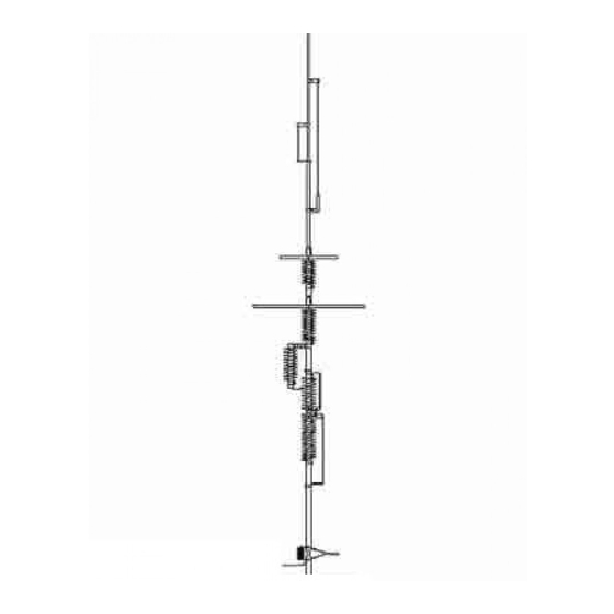
PARTS LIST A 00278SZV Tube A W/Insulator (1-1/8" X 24") B 00115BAV Tube B (1-1/8" X 48") B1 00365SZV Tube B1 W/Insulator (1-1/8" X 12") C 00145SZV Coil Assembly 80/40 Meter D 290-07 Capacitor Assembly 80/40 Meter D1 00150BAV Capacitor Bracket 80 Meter D2 00220BAV Capacitor Bracket 40 Meter E 00123BAV... - Page 14 PICTORIAL Feedline Detail -14-...
-
Page 15: Mounting Tube Installation
TECH NOTES—GROUND RADIAL SYSTEMS MOUNTING TUBE INSTALLATION When tube w/insulator (A) is ground mounted, it should be protected against corrosion if placed in concrete, damp acidic or alkaline soil. Asphalt roofing compound, polyurethane varnish or other sealant that protects against moisture may be used. - Page 16 TECH NOTES—GROUND RADIAL SYSTEMS In almost every case the efficiency of a vertical antenna will be greater if radial wires are used to improve ground conductivity as in figure 2. It’s important to note that there’s no point in cutting radials to any particular length when ground mounting because the earth will detune them anyway.
- Page 17 TECH NOTES—GROUND RADIAL SYSTEMS resistance is the textbook figure of 35 ohms. The feedpoint impedance would then be 15+0+35 = 50 ohms, and the antenna would be perfectly matched to a 50 ohm coaxial line. Since the radiation resistance is an index of the amount of applied power that is consumed as useful radiation rather than simply lost as heat in the earth or in the conductor, the radiation resistance must be kept as high as possible in relation to the total feedpoint impedance for maximum efficiency.
- Page 18 Figure 4 but require only 4 supports. These multiband radials plus additional wire for an 80 meter radial are available separately (our STR-II kit) or as part of the Butternut roof mounting kit (RMK-II). There are times when physical restrictions will dictate the use...
- Page 19 TECH NOTES—GROUND RADIAL SYSTEMS Figure 6 illustrates the construction of a multi-band radial which is resonant on 40, 20, 15 and 10 meters. Good quality 300 ohm TV ribbon lead should be used (velocity factor is critical), and the conductors should employ at least one strand of steel wire to support the weight of the radial.
- Page 20 TECH NOTES—GROUND RADIAL SYSTEMS spot, away from obstacles (including the MH or RV) that can interfere with radiation from the antenna. The second is that of installing the beat possible ground system beneath the antenna in order to minimize losses from r.f. currents flowing in the earth below the antenna.
-
Page 21: Lightning Protection
Steel TV mast sections are readily available in lengths of ten feet and the mounting posts of Butternut HF verticals will slide into those which have an outside diameter of 1 1/4 inches and a wall thickness of .058 inches. -
Page 22: Troubleshooting
TROUBLESHOOTING Check out your installation again, looking for loose connections and checking all dimensions. Then refer to the list of possible symptoms below: Symptom: Few or no signals heard: bands seem dead, SWR is very high. Look for: Open or shorted feedline, open or shorted matching line, broken connection at base of antenna (feedpoint). - Page 23 TROUBLESHOOTING Look for: Operation at high power levels in areas where salt or pollution deposits have built up on the insulators. The cure is to keep insulators clean through routine maintenance. Symptom: Intermittent operation. SWR jumps up and down suddenly, and reception is also intermittent.
-
Page 24: Limited Warranty
Such repair or replacement is the Customer's sole and exclusive remedy for a Defective Product. Specifically, Butternut is not liable (to the Customer or otherwise) for (a) any loss or damage arising in any way from a Product or from actual or anticipated sale,...
Need help?
Do you have a question about the HF9V and is the answer not in the manual?
Questions and answers