Table of Contents
Advertisement
Advertisement
Table of Contents

Related Manuals for Butternut BUT-HF6V


Summary of Contents for Butternut BUT-HF6V
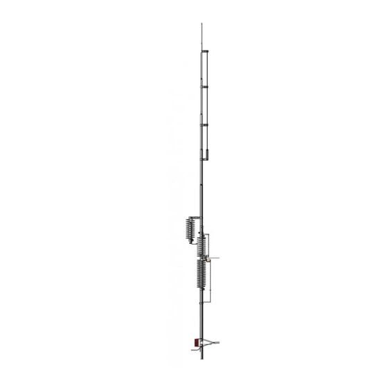
- Page 1 ® 80/40/30/20/15 and 10 Meters Six-Band Vertical Antenna BUT-HF6V BUT-HF6V-INS-Revision 1a © Butternut 2016 Artists rendition of an installation 1200 Southeast Ave. - Tallmadge, OH 44278 USA Phone: (800) 777-0703 ∙ Tech Support and International: (330) 572-3200 Fax: (330) 572-3279...
- Page 2 Introduction ® The classic Butternut HF6V 6-band vertical antenna operates on 75/80, 40, 30, 20, 15 and 10 meters. Designed with corrosion-resistant aluminum tubing, this antenna is very durable and attractive. The first L/C circuit generates enough reactance to bring the whole HF6V to resonance on 80 meters allowing it to act as a 1/4-wave radiator.
-
Page 3: Tools Required
WARNING! INSTALLATION OF ANY ANTENNA NEAR POWER LINES IS DANGEROUS Warning: Do not locate the antenna near overhead power lines or other electric light or power circuits, or where it can come into contact with such circuits. When installing the antenna, take extreme care not to come into contact with such circuits, because they may cause serious injury or death. - Page 4 Information on guying the ® ® Butternut HF6V is included in this manual. Information on guying the Butternut HF6V can be found in the section “Guying the HF6V Antenna”. BUT-GRK Ground Radial Kit for ground mounting - 160 thru 6 meter operation...
- Page 5 Mounting Tube (A) Installation When the bottom tube with insulator (A) is ground mounted, it should be protected against corrosion if placed in concrete, damp acidic or alkaline soil. Asphalt roofing compound, polyurethane varnish or other sealant that protects against moisture may be used. Concrete may be used in areas of high winds for greater strength, in which case the post may be twisted slightly during setting for easy removal later.
- Page 6 The extra radials help overcome unknown poor-soil conditions, improve bandwidth, and ® ensure the best performance efficiency possible from the Butternut HF6V antenna. Radial Wire, a 14 gauge stranded copper with black relaxed PVC insulation wire is suggested for the best results for ease of installation and being able to withstand foot traffic over the radial wires without breaking smaller gage wires.
- Page 7 A stainless steel Radial Plate is an ideal option for the radial system that is needed for the ® Butternut HF6V vertical antenna. The radial plate can be set on the ground. When the antenna is installed, run a short piece of copper strap from the radial plate to the lower connection of coil Q mounted on tube (A) of the HF6V or the optional BUT-MPS Mounting Post Sleeve.
- Page 8 2. Clean the inside of the aluminum tubing to clear out any dirt or foreign material that would cause the aluminum tubing sections to bind during assembly. Do not use any type of oil or general lubricant between the aluminum tubing sections. Oils or general lubricants can cause poor electrical connections for radio frequencies.
- Page 9 1. Check to be sure that no parts are missing (see assembled antenna pictorial page) 2. If the antenna is to be installed at ground level, plant mounting tube (A) in a hole approximately 21 inches deep so the upper end of the fiber rod insulator (feedpoint connection) is approximately 3 inches or less above ground level.
- Page 10 4. From the center of the insulator, measure downward to a point that is 13” along tube (B) and make a pencil mark. 5. From the center of the insulator, measure upward to a point that is 9-3/8" along tube (B1) and make a pencil mark.
- Page 11 9. Stretch the 80 meter (larger) coil on the coil assembly 80/40 meter (C) until the bottom of the lower clamp is even with the lower mark. Secure with a #10 flat washer, lock washer and wing nut. 10. Locate the capacitor assembly 80/40 meter (D) and install capacitor bracket 80 meter (D1) on the larger 200 pF capacitor using the installed screw.
- Page 12 15. Insert the un-slotted end of tube (E) into tube (B1) and secure with a # 8 x 1-1/2" screw, lock washer and hex nut. 16. Locate coil support tube 30 meter (O) and measure to a point 9-7/8” down from the end of the plastic insulator.
- Page 13 22. Slide the remaining clamp from the above assembly over tube (E) and position it so the coil support tube L bracket (O1) is even with fourth turn, counting from the top of the 40 meter coil on the coil assembly 80/40 meter (C) and tighten the hex nut. 23.
- Page 14 26. Locate wire clamp 0.750" 15M with insulator (N) and position it around tube (G). Final tightening and positioning will be done in a later step. 27. Insert the un-slotted end of tube (H) into the slotted end of tube (G) and secure with a # 8 x 1" screw, lock washer and hex nut.
- Page 15 32. Pass the free end of the stranded wire from wire clamp 0.500" 15M with wire (L) through the small holes in wire clamp 0.625" 15M with insulator (M) and wire clamp 0.750" 15M w/insulator (N) as shown. 33. Loop the end of the wire through the hole in wire clamp 0.875" 15M with insulator (K) sliding it on tube (F) until the mark on the wire appears.
- Page 16 39. Install coax 75 ohm matching (R) as shown placing the lug from the center conductor over the screw on tube (B) and the braid over the screw on tube with insulator (A). To aid in eliminating water damage of the coax, run it so the terminals are facing downward so water will drip down, not toward the coaxial cable.
- Page 17 Checkout and Adjustment Adjustments will have to be made before trying to transmit with this antenna system. Installations vary considerably and there are no ‘set’ measurements that will work for all the variables in the installation. The dimensions and coil settings that were used during assembly are somewhat close and may produce reasonably low VSWR readings over the entire 10, 15, 20 and 30 meter bands and over at least 250 kHz of the 40 Meter band.
- Page 18 To lower frequency, feed more of the tail back through the hole in the insulator to increase the length of the wire between wire clamp 0.500" 15M with wire (L) and wire clamp 0.875" 15M with insulator (K). A change of 2 inches will shift the VSWR curve approximately 300 kHz. 3.
- Page 19 Alternatively, to lower the frequency of lowest SWR, reconnect the coil support tube 30 meter L bracket (O1) to the next higher turn of the 40 meter coil. In some cases moving the tap point a full turn up or down may cause more of a frequency shift than is desired, in which case the entire 30 meter assembly may be rotated around tube (E) to permit adjustments of less than one full turn.
- Page 20 The 12-radial system of Figure 2 is a very good one, but it requires at least 12 tie-off points. ® Butternut has developed a multiband radial made of 300 ohm twinlead that resonates simultaneously on 40, 20, 15 and 10 meters. Four such radials offer essentially the same ground plane performance as the system of Figure 2 but require only 4 supports.
- Page 21 energy, and the pattern will not be completely omnidirectional. For true ground plane action and predominantly vertical polarization no fewer than three equally-spaced radials should be used. Figure 4 illustrates the construction of a multi-band radial which is resonant on 40, 20, 15 and 10 meters.
- Page 22 Steel TV mast sections are readily available in lengths of ten ® feet and the mounting posts of Butternut HF verticals will slide into those which have an outside diameter of 1-1/4 inches and a wall thickness of .058 inches.
-
Page 23: Lightning Protection
Lightning Protection Modern solid state amateur equipment is particularly vulnerable to damage from lightning or static induced transients that may appear on transmission lines. Troubleshooting Check out your installation again, looking for loose connections and checking all dimensions. Then refer to the list of possible symptoms below: Symptom: Few or no signals heard: bands seem dead, SWR is very high. - Page 24 Adjust coils carefully! Remember, tuning, is sharp on these bands, so it is easy to pass the resonant point, then assume erroneously that the antenna isn't tuning. BEFORE you call Butternut for help, please double check your installation, including all connections and dimensions. Tune carefully and systematically. Have SWR curves available.
- Page 25 Guying the HF6V Antenna The HF6V is designed to survive winds of up to 80 mph without guying in the absence of ice loading or heavy precipitation, but over a period of time it is to be expected that frequent or even constant flexing or vibration will reduce the chances for survival in winds that would not damage a newly installed antenna.
- Page 26 ® Butternut HF6V Parts List Part Part Description Description Number Number 00278S Tube A with Insulator, 1-1/8” dia x 24” long 00249S Coil/Capacitor Assembly - 30 Meters 00115 Tube B element, 1-1/8” dia x 48” long 00137S Coil Q Base Matching 00365S Tube B1 with Insulator, 1-1/8”...
- Page 27 HF6V Assembly with Enlarged Details [Dimension in inches. Drawings not to scale.] - 26 -...
-
Page 28: Technical Support
All products manufactured by Butternut are warranted to be free from defects in material and workmanship for a period of one (1) year from date of shipment. Butternut’s sole obligation under these warranties shall be to issue credit, repair or replace any item or part thereof which is proved to be other than as warranted; no allowance shall be made for any labor charges of Buyer for replacement of parts, adjustment or repairs, or any other work, unless such charges are authorized in advance by Butternut.
Need help?
Do you have a question about the BUT-HF6V and is the answer not in the manual?
Questions and answers