Advertisement
Quick Links
BUTTERNUT Manufacturing Co.
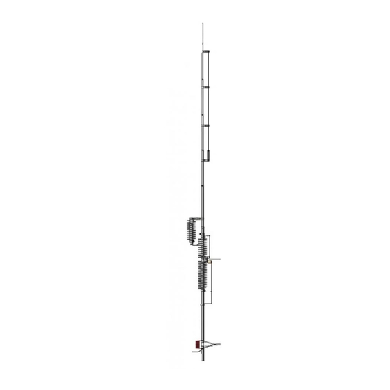
Model HF6V-X
PLEASE READ ALL INSTRUCTIONS THOROUGHLY BEFORE PROCEEDING TO ASSEMBLY.
DURING ASSEMBLY AND INSTALLATION TAKE EXTREME CARE TO AVOID CONTACTING
POWER LINES WITH ANY PART OF THE ANTENNA OR OTHER CONDUCTORS.
DO NOT INSTALL THE ANTENNA IN ANY PLACE WHERE ANY PART OF IT CAN COME INTO
CONTACT WITH POWER LINES IN THE EVENT OF STRUCTURAL FAILURE OF ANY PART OF
THE INSTALLATION OR IN THE COURSE OF NORMAL FLEXING AFTER INSTALLATION,
FOR SUCH CONTACT CAN RESULT IN DAMAGE TO PROPERTY, BODILY INJURY OR
DEATH!
IN NO CASE SHOULD THE ANTENNA BE INSTALLED IN ANY PLACE WHERE STRUCTURAL
FAILURE OF ANY PART OF THE ANTENNA OR ITS SUPPORTING SYSTEM CAN ENDANGER
PERSONS OR PROPERTY.
CAUTION! A GROUNDED ANTENNA WILL BE AT DC GROUND POTENTIAL! TO AVOID
DANGER OF SHOCK CONNECT ALL STATION EQUIPMENT TO A GOOD EARTH GROUND. IT
IS ALSO RECOMMENDED THAT ALL STATION EQUIPMENT BE DISCONNECTED FROM THE
POWER MAINS BEFORE CONNECTING THE FEEDLINE TO THE ANTENNA. PLEASE
CONSULT THE A.R.R.L. HANDBOOK OR OTHER REFERENCE MANUALS FOR ADDITIONAL
SAFETY PROCEDURES WHEN WORKING WITH ELECTRICAL EQUIPMENT.
Tools required for assembly: flat blade screwdriver, pliers and a knife. A set of nut-drivers will be
useful.
TO ASSEMBLE AN HF9V-X, FOLLOW THESE INSTRUCTIONS, THEN INSTALL THE
A-17-12 AND A6 ADAPTERS.
NOTE: A small packet of anti-seize/anti oxide compound will be found inside mounting post A. This
compound should be applied lightly to each tubing joint and to the inside of all clamps that must make
good electrical contact with the tubing sections.
Refer to the appropriate drawings and diagrams and proceed as follows:
1. Check to be sure that all parts are present (see parts pictorial page.)
2. Locate tube A w/insulator (A). This is one of two lengths of 2' x 1 1/8" tubing that has a glass-epoxy
insulating rod attached to it at one end. Tube a w/insulator (A) can be recognized by the long
machine screw passing through the tube and the insulator. Do not confuse it with the piece of the
same size and length that has the short machine screw.
3. If the antenna is to be installed at ground level, plant tube A w/insulator (A) in a hole approximately
21" (55cm) deep so that the upper end of the glass-epoxy insulator rod is approximately 5", 12 cm
above ground level. Pack earth tightly around the mounting post so that it will remain vertical.
Concrete may be used in areas of high winds for greater strength, in which case the post may be
twisted slightly during setting for easy removal later. The mounting post tube should be protected
831 North Central Avenue Wood Dale Illinois 60191-1219 Telephone 630•238•1854 Facsimile 630•238•1186
ASSEMBLY
1
Instructions
V00233-082599
Advertisement

Related Manuals for Butternut HF6V-X


Summary of Contents for Butternut HF6V-X
- Page 1 BUTTERNUT Manufacturing Co. Instructions Model HF6V-X PLEASE READ ALL INSTRUCTIONS THOROUGHLY BEFORE PROCEEDING TO ASSEMBLY. DURING ASSEMBLY AND INSTALLATION TAKE EXTREME CARE TO AVOID CONTACTING POWER LINES WITH ANY PART OF THE ANTENNA OR OTHER CONDUCTORS. DO NOT INSTALL THE ANTENNA IN ANY PLACE WHERE ANY PART OF IT CAN COME INTO...
- Page 2 ASSEMBLY against corrosion if it is to be placed in concrete or damp, acidic or alkaline soil. Asphalt roofing compound, polyurethane varnish or any other sealant that protects against moisture may be used. No such protection is required for above-ground and most ground-level installations. NOTE: hammering the mounting post into the earth may cause the insulator rod to splinter.
- Page 3 ASSEMBLY compression clamps. These clamps use a#8 x 1" machine screw, a split lockwasher and a hex nut. If a flat blade screwdriver is used to tighten the clamps do not grasp the work immediately opposite the blade in order to avoid injury if the blade slips. 11.
- Page 4 Similar precautions should be observed when using TV-style towers with locking bolts. The Butternut Roof Mounting Kit (model RMK-II) includes a protective sleeve for the mounting post tube; this tube is also available separately as model MPS for non- permanent ground-level installations.
- Page 5 ASSEMBLY assembly points in the same direction as the "L"-shaped clamp at the bottom of coil support tube 30 meter (O). Tighten the upper clamp around the insulator and set the completed coil support tube 30 meter (O)/coil/capacitor assembly 30 meter (P) assembly aside. 24.
- Page 6 CHECKOUT AND ADJUSTMENT ground system used, greater bandwidth being associated with lossy ground systems. It should be remembered that on those bands where the physical height of a vertical antenna is less than a quarter wavelength, the earth (or the resonant radial system in above-ground installations) will have a good deal to do with VSWR, antenna tuning, bandwidth, and overall performance.
-
Page 7: Theory Of Operation
THEORY OF OPERATION The HF6V-X / HF9V-X operates as a slightly extended quarter-wave radiator on 15 meters, a quarter- wave stub decoupler providing practically lossless isolation of the upper half of the antenna on that band. -
Page 8: Electrical And Mechanical Specifications
If operation is desired on 160 meters, the 17 and 12 meter bands, or even 6 meters, add-on kits requiring no "surgery" are available from your Butternut dealer. NOTE: The A-17-12 and A-6 adapters are provided with the HF9V-X. - Page 9 NOTES ON GROUND/RADIAL SYSTEMS FOR VERTICAL ANTENNAS GROUND MOUNTING A vertical antenna in its simplest form is electrically equivalent to one-half of a dipole antenna stood on end. When the antenna is mounted close to the ground, the earth below takes the place of the "missing" half of the dipole. If ground conductivity is fair to good, a short metal stake or rod may provide a sufficiently good ground connection for resonant and low SWR operation on the bands for which the antenna is designed.
-
Page 10: Parts List
PARTS LIST A V00278 Tube A W/Insulator, 1 1/8" X 24" B1 V00285 Tube B1 Section, 1 1/4" x 28" B2 V00297 Tube B2 W/Insulator, 1 1/8" x 24" B3 V00167 Tube B3, 1 1/8" x 36" C V00145 Coil Assembly 80/40 Meter D V00190 Capacitor Assembly 80/40 Meter D1 V00150 Capacitor Bracket 80 Meter D2 V00220 Capacitor Bracket 40 Meter... - Page 11 Feedline Detail 1. Use a knife to scrape 1 1/2" of enamel insulation from point A. Be sure that the copper is bright and clean. 2. Bend the clean area into a loop for connection later. The clean area may be tinned with solder.
- Page 12 IF YOU HAVE PROBLEMS... Check out your installation again, looking for loose connections and checking all dimensions. Then refer to the list of possible symptoms below: Symptom: Few or no signals heard: bands seem "dead", SWR is very high. Look for: Open or shorted feedline, open or shorted matching line, broken connection at base of antenna (feedpoint).
Need help?
Do you have a question about the HF6V-X and is the answer not in the manual?
Questions and answers