Table of Contents
Advertisement
Quick Links
Advertisement
Table of Contents

Related Manuals for Butternut HF2V


Summary of Contents for Butternut HF2V
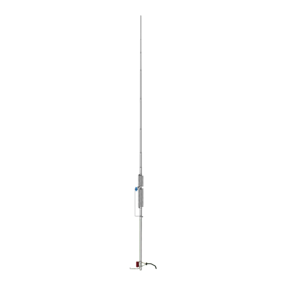
- Page 1 Butternut HF2V 80/40 Dual-Band Vertical Antenna BUT-HF2V BUT-HF2V-INS-Revision 4 © Butternut 2019 1200 Southeast Ave. - Tallmadge, OH 44278 USA Phone: (800) 777-0703 ∙ Fax: (330) 572-3279 Artists rendition of an installation Tech Support and International: (330) 572-3200...
- Page 2 Active element length on 80 & 40 meters is 32 feet Requires radial system Please - Read the entire manual to become familiar with the construction of the Butternut HF2V vertical antenna. This manual does follow the ‘classic’ design and construction methods. However, throughout the manual information has been added that varies from the ‘classic’...
-
Page 3: Tools Required
A four-point guying scheme provides the best mechanical advantage to reduce wind stress, regardless of direction. Information on guying the Butternut HF2V is included in this manual. Site Selection Ideally, select a mounting location clear from power lines, structures and other antennas by a minimum of 35 feet. - Page 4 The extra radials help overcome unknown poor-soil conditions, improve bandwidth, and ensure the best performance efficiency possible from the Butternut HF2V antenna. Radial Wire that is 14 gauge stranded copper with black relaxed PVC insulation wire is suggested for the best results.
- Page 5 The Optional Radial Plate A DXE-RADP-3 Radial Plate is an ideal option for the radial system that is needed for the Butternut HF2V vertical antenna. The radial plate can be set on the ground, or connected by means of a clamp to the lower tube of the HF2V.
- Page 6 Assembly Note: For reference purposes, a completed basic HF2V Antenna is shown at the end of this manual following the complete detailed parts list. 1. Check to be sure that no parts are missing (see assembled antenna pictorial page) 2. If the antenna is to be installed at ground level, plant mounting post (A) in a hole approximately 21 inches deep so the upper end of the fiber rod insulator is approximately 3 to 5 inches above ground level.
- Page 7 and #10 wing nuts secure the two remaining coil clamps, tightening the wing nuts only enough to hold the hardware in place. Coil adjustments will be made later. 5. Install the capacitor bracket (E) on the capacitor assembly (D) using the hardware already on the capacitor.
- Page 8 CONTACT WITH IT 15. Any length of cable having a characteristic impedance of 50 to 53 ohms may be used to feed the HF2V. 16. Install the Red Coil (Q) and the Feedpoint Connector (R1) in place as shown below. The Red Coil and the Feedpoint Connector span over the insulator between Tube (A) and Tube (B).
- Page 9 Q mounted on tube (A) of the HF2V or the optional BUT-MPS Mounting Post Sleeve. In either case, a ground wire attachment from the lower tube (A) to the Radial Plate should be made to ensure a good RF connection.
- Page 10 80 and 40 meter coils more than is possible simply by stretching the coils. Lower than normal inductance may be necessary if the HF2V is top loaded as described later for the sake of greater SWR bandwidth on 80/75 meters.
- Page 11 With a loss-free ground system the resistive part of the feedpoint impedance of the HF2V on 80/75 meters will be less than 20 ohms and the resulting mismatch with 50-ohm cable would produce SWR of greater than 2:1. Base matching coil (Q) may be...
- Page 12 It is obvious that the addition of top-loading wires to the HF2V will call for less inductance in the 80 and 40 meter tuning circuits, in which case the shorting strap for the 80 meter circuit will be needed.
- Page 13 Top-loading wires should not be attached to the very tip of the antenna because the tubing in the two uppermost sections is no stronger than it needs to be to support itself. Operation of the HF2V may be extended to the other bands through the addition of accessories without sacrificing 80 and 40 meter performance.
- Page 14 Butternut HF2V Detail Drawings (Not Scale) - 13 -...
- Page 15 Under no circumstances should guys be placed higher than one-third of the way up the antenna. The upper two-thirds of the HF2V has little more than its own weight to support, so these sections may be allowed to bend with the wind with no serious risk of damage. It is the lower third of the antenna that must support both the weight of the upper sections and the wind loading on them and are thus more likely to receive damage in severe winds.
-
Page 16: Technical Support
(1) year from date of shipment. Butternut’s sole obligation under these warranties shall be to issue credit, repair or replace any item or part thereof which is proved to be other than as warranted;...
Need help?
Do you have a question about the HF2V and is the answer not in the manual?
Questions and answers