Vinotemp WINE-MATE VINO1500SS Installation, Operation & Care Manual
Hide thumbs
Also See for WINE-MATE VINO1500SS:
- Installation instructions manual (6 pages) ,
- Installation instruction (2 pages) ,
- Installation, operation & care manual (14 pages)
Table of Contents
Advertisement
Quick Links
WINE-MATE Split System
Installation, Operation & Care Manual
V
i
n
o
t
e
V
i
n
o
t
e
READ AND SAVE THESE INSTRUCTIONS
w
w
w
.
w
i
n
e
m
a
t
e
.
c
w
w
w
.
w
i
n
e
m
a
t
e
.
c
VINO1500SS
VINO-1900SS
m
p
I
n
t
e
r
n
a
t
i
o
m
p
I
n
t
e
r
n
a
t
i
o
w
w
w
.
v
i
n
o
t
e
m
p
.
c
o
w
w
w
.
v
i
n
o
t
e
m
p
.
c
o
m
o
m
n
a
l
C
o
r
p
.
n
a
l
C
o
r
p
.
m
o
m
Advertisement
Table of Contents

Related Manuals for Vinotemp WINE-MATE VINO1500SS


Summary of Contents for Vinotemp WINE-MATE VINO1500SS
- Page 1 WINE-MATE Split System Installation, Operation & Care Manual VINO1500SS VINO-1900SS READ AND SAVE THESE INSTRUCTIONS...
-
Page 2: Table Of Contents
TABLE OF CONTENTS Important Safety Information…..........2 Features & Specifications.…………………….……………..3 Cellar Construction…………………………….……………..6 Installer’s Instruction……….….……………………………..7 Electrical Wiring……………………………………………...13 Temperature Control………………………………………...15 Care Guide…………………………………………………….16 User’ Troubleshooting…….………………………………...17 Customer Support……………………………………………20 Warranty……………………………………………………….21 - 1 -... -
Page 3: Important Safety Information
Important Safety Information WARNING: • DO NOT USE A GROUND FAULT INTERRUPTER (GFI). • A DEDICATED 20 AMP CIRCUIT IS REQUIRED. - 2 -... -
Page 4: Features & Specifications
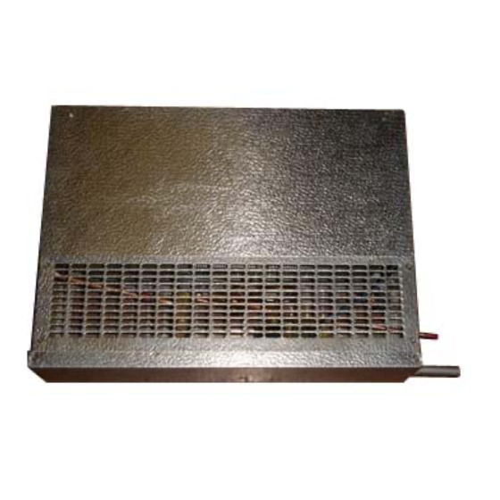
Features and Specifications • Wine-Mate split cooling systems VINO1500SS and 1900SS are designed and ° used to provide a cold temperature between 50~65 F for a properly insulated wine room at a normal environment. • The wine room will maintain humidity of 50~70% RH even when the environment becomes dry and humid. - Page 5 Evaporator Unit (liquid line solenoid valve and expansion valve installed) Temperature Controller + Air Sensor Fig. 1 WM15SFC Evaporator Unit Fig. 2 WM19SFC Evaporator Unit - 4 -...
- Page 6 Fig. 3 WM-150SCU Condensing Unit Fig. 4 Liquid Filter Fig. 5 Liquid Indicator - 5 -...
-
Page 7: Cellar Construction
Cellar Construction This is only a guide and shall be considered as minimum requirements. All interior walls and floors shall have a vapor barrier and a minimum of R11 insulation. All exterior walls and ceiling shall have a vapor barrier and a minimum of R19 insulation. -
Page 8: Installer's Instruction
WINEMATE split system is shipped as components and is ready for use only after a certified refrigeration technician has properly installed, evacuated, charged and tested the system. Proper installation is critical. Vinotemp can only warrant the quality of the components. The installation and proper operation of the system must be warranted by the installer. - Page 9 2. Discharge/Suction Valve Operation (Condensing unit) Back Position: Normal operation, process and manometer port closed Front Position: Liquid/suction line connection closed Middle Position: All ports open for evacuation, charge and manometer reading BACK POSITION FRONT POSITION MIDDLE POSITION Fig. 6 ROTALOCK Valve Operation BACK POSITION FRONT POSITION MIDDLE POSITION...
- Page 10 4. Piping, Evacuating, Charging and Starting CAUTION: • ALWAYS USE THE SUPERHEAT AND SUBCOOLING, PRESSURE READINGS TO CHARGE REFRIGERANT PROPERLY, THE LISTED CHARGES ARE FOR REFERENCE ONLY. • CHARGE 15% MORE REFRIGERANT IN THE SUMMER IF THE UNIT IS EQUIPPED WITH A LOW AMBIENT CONDITION KIT. NOTES: •...
- Page 11 Use of the adjustable pressure control (if applicable for pump-down) Suction pressure setting: Cut out=5 psig; Cut in=25 psig; Differential=20 psig Head pressure setting: Cut out=230 psig; Cut in=150 psig; Differential=80 psig It may need to adjust the setting in the field to get the right cycle time. A.
- Page 12 Use of the encapsulated pressure control (if applicable) Fixed suction pressure setting: Cut in = 32 psig; Cut out = 10 psig Fig. 10 Fixed Pressure Control Use of the condenser fan control (if applicable for low ambient kit) Head pressure setting: Cut in=170 psig; Cut out=120 psig; Differential=50 psig It closes on rise of pressure.
- Page 13 restricted Low suction pressure and low head pressure Suction line restricted Normal to high superheat and low subcooling Low suction pressure and low head pressure restricted evaporator, Low superheat and low subcooling evaporator iced k. Low suction pressure and low to normal head pressure k.
-
Page 14: Electrical Wiring
Electrical Wiring CAUTION: • USE MINIMUM 14 GAUGE WIRE.S • IF EQUIPPED WITH LOW AMBIENT CONDITION KIT, USE LOW AMBIENT TEMPERATURE WIRING DIAGRAMS. TURN OFF THE COMPRESSOR BEFORE POWER THE CONDENSING UNIT. ONLY TURN ON THE COMPRESSOR AFTER THE CONDENSING UNIT HAS BEEN POWERED FOR 24 HOURS. - Page 15 Fig. 12 Low Ambient Temperature VINO1500-1900SS Electrical Wiring Diagram - 14 -...
-
Page 16: Temperature Control
Use and Temperature Control 1. Temperature Setting • Set the temperature at 55 ° for the optimum aging of wine • On initial start-up, the time required to reach the desired temperature will vary, depending on the quantity of bottles, temperature setting and surrounding temperature. -
Page 17: Care Guide
Care Guide In general, always unplug system or disconnect power while doing care. 1. Coil Cleaning • Clean the condenser coil regularly. Coil may need to be cleaned at least every 6 months. • Unplug the system or disconnect power. •... -
Page 18: User' Troubleshooting
User’s Troubleshooting This Troubleshooting Chart is not prepared to replace the training required for a professional refrigeration service person, not is it comprehensive Troubleshooting Chart Complaint Possible Causes Response a. No power a. Check power at receptacle & fuses 1.Unit not b. - Page 19 temperature c. Ambient temperature too high c. Check for installation location d. Exhaust restricted d. Leave minimum 3 ft clearance for too high and the exhaust side and leave minimum running 1 foot clearance for the fresh air continually intake side e.
- Page 20 10.Noisy a. Mounting area not firm a. Add support to improve installation b. Loose parts b. Check fans, cabinet washers, tubing operation contact and loose screws. c. Compressor overloaded due to c. Check for airflow blockage high ambient temperatures or airflow restriction d.
-
Page 21: Customer Support
Customer Support If you still have problems, please contact us at: Vinotemp International 17631 South Susana Road Rancho Dominguez, CA 90221 Tel: (310) 886-3332 Fax: (310) 886-3310 Email: info@vinotemp.com - 20 -... -
Page 22: Warranty
BTU/H. While every effort has been made to provide accurate guidelines, VINOTEMP can not warranty its units to cool a particular enclosure. In case of failure, VINOTEMP cooling units must be repaired by the factory or its authorized agent. Repairs or modifications made by anyone else will void the warranty. - Page 23 VINOTEMP will, at its discretion, repair or replace the unit and return it free of charge to the original retail customer. If the unit is found to be in good working order, or beyond the initial twelve month period, it will be returned freight collect.
Need help?
Do you have a question about the WINE-MATE VINO1500SS and is the answer not in the manual?
Questions and answers