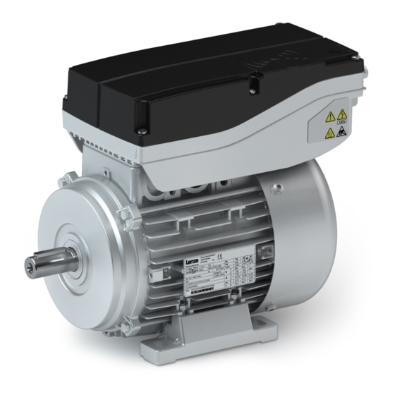
Lenze Smart motor m300 Project Planning
Three-phase ac motors
Hide thumbs
Also See for Smart motor m300:
- Mounting and switch-on instructions (76 pages) ,
- Mounting instructions (116 pages)
Table of Contents
Advertisement
Quick Links
Advertisement
Table of Contents

Related Manuals for Lenze Smart motor m300


Summary of Contents for Lenze Smart motor m300
- Page 1 Project planning EN Three-phase AC motors Lenze Smart motor m300...
-
Page 3: Table Of Contents
Contents Contents About this document Document description Further documents Notations and conventions Product information Product description Identification of the products Features The modular system Mounting positions Information on project planning Safety instructions Basic safety instructions Application as directed Residual hazards Drive dimensioning Final configuration Surface and corrosion protection... - Page 4 Contents Product extensions Motor connection Connection via terminal box Connection via QUICKON V2 connector Connection via M15 connector Connection via M12 connector Brakes Spring-applied holding brake Brake resistors Accessories NFC adapter QUICKON connector UMCLN_SGG_100181 Purchase order Notes on ordering Product codes Environmental notes and recycling Appendix Good to know...
-
Page 5: About This Document
The documentation must always be complete and in a perfectly readable state. • Further documents Information and tools with regard to the Lenze products can be found on the Internet: www.Lenze.com à Downloads... -
Page 6: Notations And Conventions
About this document Notations and conventions Notations and conventions This document uses the following conventions to distinguish different types of information: Numbers Decimal separator Point In general, the decimal point is used. Example: 1 234.56 Warning UL warning Are used in English and French. UR warning Text Programs... -
Page 7: Product Information
This led to a large number of different drive variants.. Things are different with the Lenze Smart Products: Due to the possibility of freely adjusting the motor speed within a range from 500 – 2600 rpm, very different speeds can be enabled with one single drive variant The cost and effort involved in design, selection, procurement and storage are thus reduced considerably. - Page 8 Only an NFC-capable Android smartphone or the Lenze NFC adapter for PCs is needed as a tool. The data can therefore be read and written when the drive is in a de-energised state –...
- Page 9 Contactor and motor protection functions integrated The Lenze Smart Products can be started and stopped by mean of digital inputs. It is also possible to switch between different speeds and rotating directions. Up to 5 different speed modes (e.
-
Page 10: Identification Of The Products
Product information Identification of the products Application examples Roller conveyors with belt ejector Belt conveyors Identification of the products Product name of the motor Product series Type Size Overall length Number of pole Motor pairs MSEMAXX063-42 (without built-on MSEMAXX080-32 accessories) MSEMA 2 (4-pole) MSEMABR063-42... -
Page 11: The Modular System
Product information The modular system The modular system Values printed in bold are standard designs. Values that are not printed in bold are potential extensions, some of them including a surcharge. Motor MSEMA☐☐063-42 MSEMA☐☐080-32 Technical data Max. torque Rated torque 1.75 Speed setting range -2600 ... -
Page 12: Mounting Positions
Product information The modular system Mounting positions Mounting positions Positions of the connections Mains connection Control terminal Cable gland for terminal box M12 connector QUICKON V2 connector M15 connector Position of the manual release lever... -
Page 13: Information On Project Planning
Information on project planning Safety instructions Basic safety instructions Information on project planning Safety instructions Basic safety instructions Disregarding the following basic safety instructions and safety information may lead to severe personal injury and damage to property! Only use the product as directed. •... -
Page 14: Residual Hazards
Information on project planning Safety instructions Residual hazards Residual hazards Even if notes given are taken into consideration and protective measures are implemented, the occurrence of residual risks cannot be fully prevented. The user must take the residual hazards mentioned into consideration in the risk assessment for his/her machine/system. -
Page 15: Drive Dimensioning
With the «Drive Solution Designer«, you can design the drive both quickly and to a high quality. The software contains profound and proven expertise with regard to drive applications and mechatronic drive components. Please get in touch with your Lenze representative. Workflow Mains operation... - Page 16 Information on project planning Drive dimensioning Installation height amsl ≤ 1000 m ≤ 2000 m ≤ 3000 m ≤ 4000 m Correction factor 0.95 Determine product on the basis of the forces Transmission element Gear wheels Sprockets Toothed belt pulleys Narrow V-belt ( depending on the ( depending on the...
-
Page 17: Final Configuration
STOP: 0 rpm Output speed 2 [500/i ... 2600/i] rpm CW rotation: > 0 rpm Output speed 3 Lenze Smart Motor with gearbox: The ratio i is Output speed 4 taken into account when calculating the output Output speed 5 speed. -
Page 18: Surface And Corrosion Protection
Information on project planning Final configuration Surface and corrosion protection Surface and corrosion protection Depending on the ambient conditions, the surface and corrosion protection system (called OKS) offers tailor-made solutions for optimum protection. Various surface coatings ensure reliable functioning even at high air humidity, in outdoor installations, or in the presence of atmospheric contamination. -
Page 19: Information On Mechanical Installation
Ambient media − especially chemically aggressive ones − may damage shaft sealing rings, • lacquers and plastics. Lenze offers special surface and corrosion protection in this case. • NOTICE Bearing damage caused by unbalance! Shafts with keyway are balanced with a half featherkey! ▶... -
Page 20: Information On Electrical Installation
Information on electrical installation Important notes Information on electrical installation Important notes DANGER! Risk of injury and risk of burns from dangerous voltage Power terminals may also carry voltage in the switched-off state or when the motor is stopped and may cause life-threatening cardiac arrhythmia and serious burns. ▶... -
Page 21: Connection According To En
Information on electrical installation Connection according to EN Connection according to EN The following data is valid for a three-phase mains connection with 400 V. Mains connection with QUICKON connector Motor MSEMA☐☐063-42 MSEMA☐☐080-32 Connection Laying system Connection type QUICKON connector Cable type Flexible Cable cross-section... - Page 22 Information on electrical installation Connection according to EN Single drive connection according to EN IEC 60204−1 3/N/PE AC 400/480 V SELV/PELV F1 … F3 F1 … F3 DC 24 V (+19.2 … +28.8 V) max. 50 mA n. c. L2 L3 Rb1 Rb2 L2 L3 Rb1 Rb2...
- Page 23 Information on electrical installation Connection according to EN Group drive connection according to EN IEC 60204−1 F1 … F3 PE L1 L2 L3 PE L1 L2 L3 PE L1 L2 L3 PE L1 L2 L3 PE L1 L2 L3 Max. total rated mains currents at 40 °C for different cable cross-sections Cable installation in accordance EN IEC 60204−1...
-
Page 24: Connection According To Culus
Information on electrical installation Connection according to cULus Connection according to cULus The following data is valid for a three-phase mains connection with 480 V. Mains connection with QUICKON connector Motor MSEMA☐☐063-42 MSEMA☐☐080-32 Connection Connection type QUICKON connector Cable cross-section Typ. - Page 25 Information on electrical installation Connection according to cULus General UL notes WARNING! ▶ UL marking ▶ Use 75 °C copper wire only, except for control circuits. ▶ Maximum conductor size is AWG14. ▶ Cord connected drives are for use only in NFPA 79 applications. ▶...
- Page 26 Information on electrical installation Connection according to cULus Fuse data (F1 ... F3) Motor MSEMA☐☐063-42 MSEMA☐☐080-32 Cable installation in accordance NFPA 70, NFPA 79 with Fuse Standard UL 248 Typ. Rated current Max. rated current Semiconductor fuse Standard UL 248 Typ.
- Page 27 Information on electrical installation Connection according to cULus Max. total rated mains currents at 40 °C for different cable cross-sections Cable installation in accordance NFPA 70, NFPA 79 with Main cable Cable cross-section Stub Cable cross-section Fuse Typ. Rated current Max.
-
Page 28: Technical Data
The rated data apply to the operating mode S1 (acc. to EN 60034-1). NOTICE In case of other operating conditions, the achievable values can differ for those mentioned. ▶ In case of extreme operating conditions, please get in touch with your Lenze representative. -
Page 29: Standards And Operating Conditions
The Electrical Equipment (Safety) Regulations 2016 S.I. 2021/745 The Ecodesign for Energy-Related Products and Energy Information Regulations 2021 Approvals GB Standard 12350-2009 for USA and Canada (requirements of the CSA 22.2 No.14) Industrial Control Equipment, Lenze File cULus UL 61800-5-1 No. E132659... -
Page 30: Protection Of Persons And Device Protection
Technical data Standards and operating conditions Protection of persons and device protection Protection of persons and device protection Degree of protection EN IEC 60529,EN IEC Information applies to the mounted and ready- IP55 60034-5 for-use state Type 12 NEMA NEMA 250 Type 4 indoor only Depending on the configuration Insulation resistance... -
Page 31: Environmental Conditions
Technical data Standards and operating conditions Environmental conditions Environmental conditions Climate 1K3 (-30 ... +60°C) <3 months Storage EN 60721-3-1:1997 1K3 (-30 ... +40 °C) >3 months Transport EN 60721-3-2:1997 2K3 (-30 ...+70 °C) EN 60721-3-3:1995 + Operation 3K3 (-30 ...+40 °C) Operation A2:1997 Site altitude... -
Page 32: Radial Forces And Axial Forces
Technical data Radial forces and axial forces Radial forces and axial forces The values for the bearing service life L refer to an average speed of 2000 rpm for the motor. Depending on the ambient temperatures, they are additionally limited by the grease lifetime. Data for axial forces refer to the maximum radial force with the corresponding bearing service life. -
Page 33: Rated Data
Technical data Rated data Application of force at l Motor MSEMA Size 063-42 080-32 Bearing service life 10000 h Radial force rated Min. axial force rated -600 -1090 ax,- Max. axial force rated Fax,+ Bearing service life 20000 h Radial force rated Min. -
Page 34: Ecodesign Directive
Efficiency at 75 % rated load η Efficiency at 50 % rated load Efficiency level Name of the manufacturer Lenze SE · Hans-Lenze-Str. 1 · 31855 Aerzen · GERMANY Commercial register number Hannover HRB 204803 Model identifier of the MSEMA□□063-42 MSEMA□□080-32... -
Page 35: Torque Characteristics
Technical data Torque characteristics Torque characteristics MSEMA☐☐063-42 1000 1500 2000 2500 3000 r/min Output torque Starting torque MSEMA☐☐080-32 1000 1500 2000 2500 3000 r/min Output torque Starting torque... -
Page 36: Dimensions
Technical data Dimensions Basic dimensions Dimensions Basic dimensions MSEMA☐☐063-42 Design B3 Dimensions Length of motor options With brake Δ L... - Page 37 Technical data Dimensions Basic dimensions MSEMA☐☐063-42 Design B5 (FF115) Dimensions Length of motor options With brake Δ L...
- Page 38 Technical data Dimensions Basic dimensions MSEMA☐☐063-42 Design B14 (FT75) Dimensions Length of motor options With brake Δ L...
- Page 39 Technical data Dimensions Basic dimensions MSEMA☐☐080-32 Design B3 Dimensions Length of motor options With brake Δ L...
- Page 40 Technical data Dimensions Basic dimensions MSEMA☐☐080-32 Design B5 (FF165) Dimensions Length of motor options With brake Δ L...
- Page 41 Technical data Dimensions Basic dimensions MSEMA☐☐080-32 Design B14 (FT100/130) Dimensions Length of motor options With brake Δ L...
-
Page 42: Product Extensions
Connection via terminal box Product extensions Motor connection The Lenze Smart Motor can be simply connected via connectors (QUICKON or M15 for power connection, M12 for control terminals). The power connection can alternatively be established in the terminal box via cable glands using spring terminals. -
Page 43: Connection Via M15 Connector
Product extensions Motor connection Connection via M15 connector Connection via M15 connector Mains connection X3 M15 power without temperature sensor Contact Name Meaning Not assigned Mains connection Phase L1 Mains connection Phase L2 Mains connection Phase L3 PE conductor... -
Page 44: Connection Via M12 Connector
Product extensions Motor connection Connection via M12 connector Connection via M12 connector Control connections with M12 connectors Via the digital inputs of the two M12 control connections, it is possible to switch between different speeds and directions of rotation. Up to 5 different speed settings (e. g. creep speed and normal speed in both directions, as well as stop) can thus be selected. -
Page 45: Brakes
Product extensions Brakes Brakes The motors can be ordered with a spring-applied brake to allow stopping or deceleration of the moving masses. The spring-applied brake operates according to the closed-circuit principle. In the deenergized state, the brake is closed, preventing possible movement of the motor shaft or the load after switching off or in the event of a power failure. -
Page 46: Spring-Applied Holding Brake
Product extensions Brakes Spring-applied holding brake Spring-applied holding brake Versions Standard 1 x 10 switching cycles, repeating 1 x 10 switching cycles, repeating Long-life 10 x 10 Switching cycles, repeating 15 x 10 Switching cycles, repeating Control Via internal electronics Holding brake, active when equipment deenergized Degree of protection Without manual release lever... - Page 47 Product extensions Brakes Spring-applied holding brake Manual release lever When ordering, specify the position of the manual release lever (T, L, R or B). Terminal box and manual release lever are not possible in the same position! Δk Motor Brake size Dimensions Δ...
-
Page 48: Brake Resistors
Brake resistors Brake resistors The Lenze Smart Motor can be braked in a guided manner along a ramp. If large amounts of regenerative energy are produced during braking, they must be absorbed by a brake resistor. In addition to a brake resistor (10 W) mounted inside the terminal box, another brake resistor (20 W) can also be connected externally alongside the terminal box via the terminal X4. -
Page 49: Accessories
Accessories NFC adapter The settings of the Lenze Smart Products can be made with an NFC-capable Android smartphone or a PC. If a PC is used to make the settings, the »EASY Starter« engineering tool must be used to do this (»EASY Advanced« software licence). Communication takes place via the NFC adapter. -
Page 50: Quickon Connector
Accessories QUICKON connector QUICKON connector With the QUICKONconnectors, the mains connection is available in a pluggable version with a commonly used standard. Nuts for QUICKON connection For fast and easy QUICKON connection, the following nuts (counterparts) can be fitted to the connecting cable. -
Page 51: Umcln_Sgg_100181
Accessories UMCLN_SGG_100181 QUICKON V2 components for cable cross-section 2.5 ... 6 mm² Order code Type QUICKON V2 H-distributor • Number of poles: 5 • Connection cross-section: 6 mm² • Cable diameter: 9 ... 20 mm EWS0114 • Connection frequency: ≥ 50 •... -
Page 52: Purchase Order
Purchase order Notes on ordering Purchase order Notes on ordering Order accessories separately. Motor without brake Motor Design Output flange Product extension Motor connection Brake resistor MSEMAXX063-42 Terminal box Without QUICKON connector Internal FT75 M15 connector External FF115 MSEMAXX080-32 FT100/FT130 FT165 Motor with brake Motor... -
Page 53: Product Codes
Product codes Product codes Motor product code Example Meaning Variant Product code Product family Motor Product type Smart Motor Cooling Integral fan Internal key Built-on accessories Without built-on accessories Brake Size Overall length Number of pole pairs 4-pole motors Design types Internal key Approval CE;... -
Page 54: Environmental Notes And Recycling
Lenze products and their packaging: Lenze products are partly subject to the EU Directive on the restriction of certain hazardous substances in electrical and electronic equipment 2011/65/EU: RoHS Directive [UKCA: S.I. 2012/3032 - The Restriction of the Use of Certain Hazardous Substances in Electrical and Electronic Equipment Regulations 2012] . -
Page 55: Appendix
Appendix Good to know Operating modes of the motor Appendix Good to know Operating modes of the motor Operating modes S1 ... S10 as specified by EN 60034-1 describe the basic stress of an electrical machine. In continuous operation a motor reaches its permissible temperature limit if it outputs the rated power dimensioned for continuous operation. -
Page 56: Enclosures
Appendix Good to know Enclosures Intermittent operation S3 Non-intermittent periodic operation S6 Sequence of identical duty cycles comprising operation with a constant Sequence of identical duty cycles comprising operation with a constant load and subsequent standstill. Start-up and braking processes do not load and subsequent no-load operation. - Page 60 © 10/2021 · 3.0 · www.Lenze.com...
Need help?
Do you have a question about the Smart motor m300 and is the answer not in the manual?
Questions and answers