
Related Manuals for Hisense AS-07HR4SYDDEB5


Summary of Contents for Hisense AS-07HR4SYDDEB5
- Page 1 Version: 1.1 2018 BLACK Star Classic A R410A AS-07HR4SYDDEB5 AS-09HR4SYDDEB35 AS-12HR4SVDDEB15 Hisense Corporation...
-
Page 2: Table Of Contents
Contents 1. S afety C onsiderations .......................... 4 2. P roduct S pecifications .......................... 6 3. P roduct P icture a nd D rawing ...................... 1 3 3-‐1. ... -
Page 3: Safety C Onsiderations
1. Safety C onsiderations IMPORTANT! Please Read Before Starting This air conditioning system meets strict safety and operating standards. As the installer or service person, it is an important part of your job to install or service the system, so it operates safely and efficiently. - Page 4 possible fire hazard. When Transporting Be careful when picking up and moving the indoor and outdoor units. Get a partner to help, and bend your knees when lifting to reduce strain on your back. Sharp edges or thin aluminum fins on the air conditioner can cut your fingers.
-
Page 5: Product S Pecifications
2. Product S pecifications Note: “**” mean code of Front Panel(See in 3-1 .Product Pictures). Model No. AS-09HR4SYDDEB35 AS-12HR4SVDDEB15 AS-07HR4SYDDEB5 Type T1, H/P, ON/OFF T1, H/P, ON/OFF T1, H/P, ON/OFF Ratings Cooling Capacity 2100 2500 3200 Heating Capacity 2200... - Page 6 (A)) Mid(dB (A)) Low(dB (A)) Outdoor Unit Noise Level dB (A) Power Supply Voltage, Frequency, Phase 220-240V~,50Hz,1P 220-240V~,50Hz,1P 220-240V~,50Hz,1P Cooling Rated Current Heating 13.3 19.2 System pressures in cooling rated conditions Max suction pressure Max discharge pressure 4.15 4.15 4.15 System Compressor Compressor type...
- Page 7 Indoor Unit Net Weight (Kg) Outdoor 21.5 Unit Indoor Unit Packing Dimensions WxHxD (mm) Outdoor 780×530×315 780×530×315 830×530×315 Unit Indoor Unit Gross Weight (Kg) Outdoor 28.5 Unit...
-
Page 8: Product P Icture A Nd D Rawing
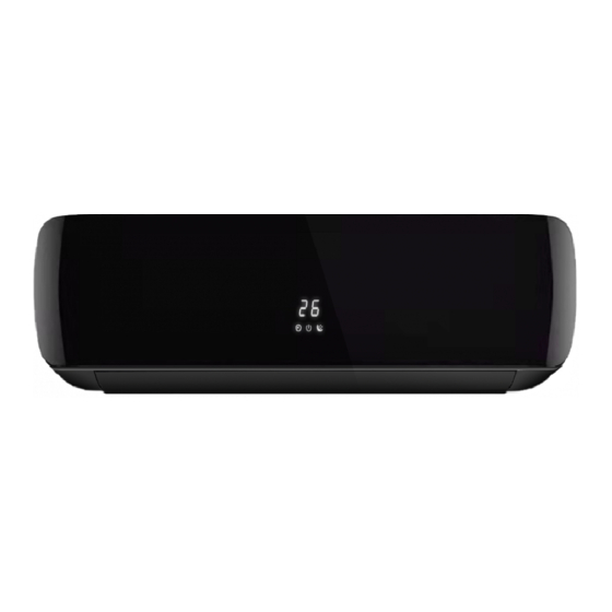
3. Product P icture a nd D rawing 3-‐1. P roduct P ictures Indoor units: Front Panel View... - Page 9 Outdoor Units: V( W1M) X( W1T) Unit View F( W2M) D( W5F) Unit View W( W1D) B( W2T) Unit View Y( W1R) Unit View...
-
Page 10: 3--2. P Roduct D Imensions
Remote controller: Model View 3-‐2. P roduct d imensions Indoor units: Model (mm) (mm) AS-07HR4SYDDEB5 AS-09HR4SYDDEB35 AS-12HR4SVDDEB15... - Page 11 Outdoor units: Model (mm) (mm) (mm) (mm) (mm) (mm) (mm) AS-07HR4SYDDEB5 AS-09HR4SYDDEB35 AS-12HR4SVDDEB15 Note: “**” mean code of Front Panel.
-
Page 12: Installation I Nstruction
4. Installation I nstruction To prevent abnormal heat generation and the possibility of fire, do not place obstacles, enclosures and grilles in front of or surrounding the air conditioner in a way that may clock air flow. And, more than 1 meter away from any antenna or power lines or connecting wires used for TV, radio, telephone, security system, or intercom. - Page 13 table 1 Standard Max. Max. Additional Pipe Size Capacity Length Elevation Length Refrigerant (Btu/h) LIQUID B (m) A (m) (g/m) 3/8"(Ø9.52) 1/4"(Ø6.35) 5k~14k 1/2"(Ø12.7) 1/4"(Ø6.35) * If total tubing length becomes 7.5 to 15 m (max.), charge additional refrigerant as the table1 for reference.
- Page 14 Recommended Wire Diameter:...
-
Page 15: 4--2. E Lectric W Iring D Iagram
4-‐2. E lectric W iring D iagram Model Indoor u nit D iagram Outdoor u nit D iagram AS-07HR4SYDDEB5 1565602 1406947 AS-09HR4SYDDEB35 1565602 1406947 AS-12HR4SVDDEB15 1565602 1406947 Note: “**” mean code of Front Panel. - Page 16 Outdoor: 1406947...
-
Page 17: 4--3. R Efrigerant F Low S Ystem
4-‐3. R efrigerant F low S ystem NOTE: In different models, the throttle assembly may be Capillary or Electronic expansion valve. -
Page 18: 4--4. A Ir P Urging A Nd L Eakage T Est
4-‐4. A ir P urging a nd L eakage T est 1. Connect charging hose of manifold valve to charge end of low pressure valve (both high/low pressure valves must be tightly shut). 2. Connect joint of charging hose to vacuum pump. 3. -
Page 19: 4--5. T Est R Unning
4-‐5. T est R unning △ Check after Installation Items to be checked Possible malfunction Has it been fixed firmly? The unit may drop, shake or emit noise. It may cause insufficient Have you done the refrigerant leakage test? cooling(heating)capacity Is heat insulation sufficient? It may cause condensation and dripping. -
Page 20: Function O Peration
5. Function O peration 5-‐1. O peration R ange ( cooling a nd h eating) Argentina Model : Temperature Indoor Air Intake Temp. Outdoor Air Intake Temp Maximum COOLING Minimum Maximum... - Page 23 Function Instruction △ 1. Major general technical parameters 1-1 Remote receiver distance(front of the air conditioner): 8 m. 1-2 Remote receiver angle: Less than 60 degrees. 1-3 Temperature control accuracy: ±1℃. 1-4 Time error: Less than 1%.、 2. Functions of the controller 2-1 Display panel I.
- Page 24 flash for 5 seconds while displayed. Running LED: It is on during operation. It is flashing when the unit defrost. TIMER LED: When the timer mode works, the LED will be lighted. Sleep LED: When the sleep mode works, the LED will be lighted, and after 10s, the LED will be off. Compressor LED:...
- Page 25 OFF-Timer setting less than 8 hours, it will keep the Sleep mode till the OFF-Timer setting; if the OFF-Timer setting more than 8 hours, it will cancel the OFF-Timer setting after the Sleep mode OFF. (3)When the Sleep mode is select with Cooling mode, if the room temperature not less than 26℃, the setting temperature will not be adjusted, otherwise, the setting temperature will be raised by 1℃...
- Page 26 3-6-2 Indoor fan operation (1)When the indoor fan keep in running condition, this operation state could be controlled by the remote control with High, Median, Low and Automatic setting. (2)When the appliance is set Automatic condition in the Cool mode for the first time, the fan speed will run at Low setting.
- Page 27 When the appliance run in Heat mode condition, the indoor fan motor operation is shown as following to prevent the cooling air come out during the appliance operation. When the appliance turn in the anti-cold air system in the Extra-LOW (Tapped motor set in LOW, sic passim) during the compressor operation, the louver swang to the Cool air protection position, the louver recovers to the original position after the air volume change to LOW.
- Page 28 position plus 5º. 4-3-8-4 Outdoor fan The outdoor fan speeds except single speed motor can be changed according to outdoor ambient temperatures. 3-7-6 4-way valve State: It is electrified in heating. Switchover: When initially powered on for heating, the 4-way valve is activated immediately. In the change from cooling to heating, it needs an interval of 50 seconds for the 4-way valve to change over from being interrupted to being activated.
-
Page 29: 5--3. S Pecial F Unction F Nstruction
≥2 Dehumidifying area II: The compressor stops for 5 minutes and operators for 5 minutes at the lowest frequency. Dehumidifying area III: The compressor stops. 3-10 Fan Only Mode Operation During the appliance run in this mode, the compressor and outdoor fan stop, the indoor fan operate under the pre-setting of air volume, and the louver swing, and the indoor fan speed same as the Heating Mode. -
Page 30: Electrical C Haracteristics
6-‐1. P rint C ircuit B oard ( Indoor & O utdoor) Print Circuit Board of Print Circuit Board of Model Indoor unit Indoor unit AS-07HR4SYDDEB5 1553856 AS-09HR4SYDDEB35 1553856 AS-12HR4SVDDEB15 1553856 Note: “**” mean code of Front Panel. - Page 31 1553856...
-
Page 32: 6--2. F An M Otor
6-‐2. F an M otor Drawings attached: INDOOR AC FAN OUTDOOR AC FAN Test in resistance. TOOL: Multimeter. Test the resistance of the main winding. The indoor fan motor is fault if the resistance of main winding 0(short circuit)or∞(open circuit). Test in voltage TOOL: Multimeter. -
Page 33: 6--3. T Emperature S Ensor
Indoor DC Fan Motor Outdoor DC Fan Motor 6-‐3. T emperature S ensor Parameter table attached: THE PARAMETER OF THE INDOOR COIL AND INDOOR ROOM SENSOR (R(0)=15k B(0/100)=3450) Temperature(℃) Resistance(k) Voltage(V) Temperature(℃) Resistance(k) Voltage(V) 38.757 0.58143512 4.292 2.715076661 36.844 0.60795346 4.137... - Page 34 20.611 0.99179340 2.706 3.266717909 19.678 1.02913875 2.615 3.305249514 18.794 1.06721353 2.528 3.342947037 17.954 1.10609872 2.444 3.380169671 17.158 1.14565549 2.363 3.416856492 16.401 1.18599135 2.286 3.45247766 15.683 1.22696435 2.211 3.487894953 1.26865672 2.139 3.522585993 14.351 1.31098658 2.07 3.556485356 13.734 1.35393437 2.003 3.590032381 13.148 1.39741342 1.939 3.622673675...
- Page 35 121.1 4.4489346 10.06 2.0071828 114.5 4.4208494 9.634 1.9554275 108.2 4.3912338 9.229 1.9045359 102.3 4.3606138 8.842 1.8542907 96.73 4.3287389 8.474 1.8049757 91.51 4.2958408 8.123 1.7564762 4.2574257 7.789 1.7089385 81.97 4.2265649 7.47 1.6622163 77.62 4.1902397 7.165 1.6162869 73.52 4.1527338 6.875 1.5714286 69.05 4.107674 6.597 1.5272955...
-
Page 36: Trouble S Hooting
7.Trouble S hooting 7-‐1. E rror C ode T able 7.1 The LED of indoor display board will show the error sequence automatically when the unit has the following trouble. Remark: Light o Flash x OFF Error ★... - Page 37 High or Low pressure The pressure switch is working protection for outdoor The pressure switch is invalid uint The outdoor control board is invalid The failure for The indoor room temperature sensor loose; temperature sensor of The indoor room temperature sensor is failure; indoor room The indoor control board is failure.
Need help?
Do you have a question about the AS-07HR4SYDDEB5 and is the answer not in the manual?
Questions and answers