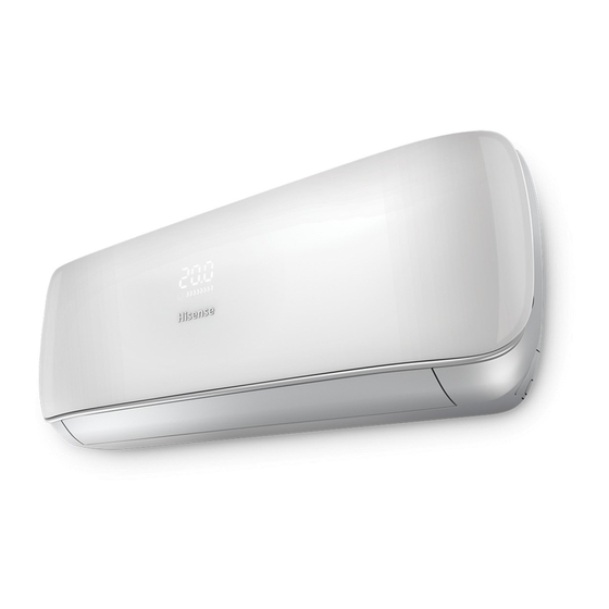
Hisense AMS-07UR4SNVT4 Service Manual

Hisense AMS-07UR4SNVT4 Service Manual

Multi-split type air conditoner indoor and outdoor units

Advertisement

MULTI-SPLIT TYPE AIR CONDITONER
SERVICE    MANUAL       

INDOOR UNIT:

AMS-07UR4SN(VG/VT/VL/VQ/UP/UL/UQ/NS/ZC/ZA/NT/NK/NM/VM)4
AMS-09UR4SN(VG/VT/VL/VQ/UP/UL/UQ/NS/ZC/ZA/NT/NK/NM/VM)4
AMS-12UR4SN(VG/VT/VL/VQ/UP/UL/UQ/NS/ZC/ZA/NT/NK/NM/VM)4
AMS-07/09/12UR4SG(NK/NM/VT/VQ)4
AMS-09/12UR4SPSC4
AMS-18U4SV(VG/VQ/VL/VT/UP/UL/UQ/NT/NK/NM)4
AMD-09UX4SJD
AMD-12UX4SJD
AMD-18UX4SJD
AMC-12UX4SAA
AMC-18UX4SAA

OUTDOOR UNIT:

AMW2-16U4SGC1
AMW2-16U4SGD1
AMW2-20U4SNC1
AMW2-20U4SZD1
AMW3-20U4SZD1
AMW3-24U4SAD1
AMW4-28U4SAD1
AMW4-36U4SAD1
Hisense Corporation
 
V:7.1
AMV-12UR4SA
AMV-18UR4SA
AS-09/12UR4SVETD5(TG5/TC5/TE5/TF5)
AS-18UR4SFATD5(TD5/TG5/TC5)
AMW3-20U4SZD
AMW3-24U4SZD
AMW3-24U4SKC
AMW4-28U4SKC
AMW4-36U4SAC

Advertisement

Table of Contents
loading

Summary of Contents for Hisense AMS-07UR4SNVT4

  • Page 1: Indoor Unit

    SERVICE    MANUAL          V:7.1 ● INDOOR UNIT: AMS-07UR4SN(VG/VT/VL/VQ/UP/UL/UQ/NS/ZC/ZA/NT/NK/NM/VM)4 AMS-09UR4SN(VG/VT/VL/VQ/UP/UL/UQ/NS/ZC/ZA/NT/NK/NM/VM)4 AMS-12UR4SN(VG/VT/VL/VQ/UP/UL/UQ/NS/ZC/ZA/NT/NK/NM/VM)4 AMS-07/09/12UR4SG(NK/NM/VT/VQ)4 AMS-09/12UR4SPSC4 AMS-18U4SV(VG/VQ/VL/VT/UP/UL/UQ/NT/NK/NM)4 AMD-09UX4SJD AMV-12UR4SA AMD-12UX4SJD AMV-18UR4SA AMD-18UX4SJD AS-09/12UR4SVETD5(TG5/TC5/TE5/TF5) AMC-12UX4SAA AS-18UR4SFATD5(TD5/TG5/TC5) AMC-18UX4SAA ● OUTDOOR UNIT: AMW2-16U4SGC1 AMW3-20U4SZD AMW2-16U4SGD1 AMW3-24U4SZD AMW2-20U4SNC1 AMW3-24U4SKC AMW2-20U4SZD1 AMW4-28U4SKC AMW3-20U4SZD1 AMW4-36U4SAC AMW3-24U4SAD1 AMW4-28U4SAD1 AMW4-36U4SAD1 Hisense Corporation...
  • Page 2: Table Of Contents

    Table of Contents Page 1.OPERATING RANGE 2.SPECIFICATION 2-1 Unit specifications 2-2 Major component specifications 2-3 Other component specifications 3.OUTLINES AND DIMENSIONS 3-1 INDOOR 3-2 OUTDOOR 4.REFRIGERANT FLOW DIAGRAM 4-1 Refrigerant flow diagram 4-2 Evacuation procedures 4-3 Evacuation direction 4-4 Air flow and ESP Chart(Duct type) 5.ELECTRICAL DATA 5-1 Electric wiring diagrams 5-2 Electric control...
  • Page 3: 1.Operating Range

    Temperature Indoor Air Intake Temp. Outdoor Air Intake Temp 43 ℃ D.B./26℃ W.B. Maximum 32℃ D.B./23℃ W.B. COOLING 21 ℃ D.B./15℃ W.B. 21℃ D.B./15℃ W.B. Minimum Maximum 27℃ D.B./18℃ W.B. 24℃ D.B./18℃ W.B. HEATING Minimum 20℃ D.B/≤15℃ W.B -10℃ D.B./-11℃ W.B.
  • Page 4: Unit Specifications

    2-1. Unit specifications 2-1-1.OUTDOOR UNIT Model AMW4-28U4SKC AMW3-24U4SKC AMW2-20U4SNC1 AMW2-16U4SGC1 Function Cooling Heating Cooling Heating Cooling Heating Cooling Heating Power supply AC 220V~240V/50Hz Capacity Dehumidification l /h ---- ---- ---- ---- ---- ---- ---- ---- Capacity Air flow ---- ---- ---- ---- ----...
  • Page 5 Model AMW3-20U4SZD AMW3-24U4SZD AMW4-36U4SAC Function Cooling Heating Cooling Heating Cooling Heating Power supply AC 220V~240V/50Hz Capacity Dehumidification l /h ---- ---- ---- ---- ---- ---- Capacity Air flow ---- ---- ---- ---- ---- ---- 8.55 Rated current 8.58 10.0 14.5 14.0 Rated input 1.87...
  • Page 6 Model AMW2-16U4SGD1 AMW2-20U4SZD1 AMW3-20U4SZD1 AMW3-24U4SAD1 Function Cooling Heating Cooling Heating Cooling Heating Cooling Heating Power supply a.c 220V~240V/50Hz Capacity Capacity Dehumidification l /h ---- ---- ---- ---- ---- ---- ---- ---- Air flow ---- ---- ---- ---- ---- ---- ---- ---- Rated current Rated input...
  • Page 7 Model AMW4-28U4SAD1 AMW4-36U4SAD1 Function Cooling Heating Cooling Heating Power supply a.c 220V~240V/50Hz Capacity Capacity Dehumidification l /h ---- ---- ---- ---- Air flow ---- ---- ---- ---- Rated current 13.2 12.4 Rated input 2.98 Electrical Auxiliary heater data Power factor 99.90% 99.90% Max.
  • Page 8 2-1-2.INDOOR UNIT AMS-12UR4SN AMS-07/09UR4SN AMS-18UR4SV(VG4/VL (VG/VT/VL/VQ/UP/UL/U Model (VG/VT/VL/VQ/UP/UL/UQ/ 4/VT4/UP4/UL4/UQ4/V Q/NS/ZC/ZA/NT/NK/NM/V Q4/NT4/NK4/NM4) NS/ZC/ZA/NT/NK/NM/VM) 4 M)4 Function Cooling Heating Cooling Heating Cooling Heating Power supply AC 220V~240V/50Hz Capacity 2.1/2.6 2.5/3.0 Dehumidification l /h ---- ---- ---- Capacity Air flow Running current Rated input 0.04 0.04 0.04...
  • Page 9 AMS-07/09UR4SG AMS-12UR4SG Model (NK/NM/VT/VQ)4 (NK/NM/VT/VQ)4 Function Cooling Heating Cooling Heating Power supply AC 220V~240V/50Hz Capacity 2.1/2.6 2.5/3 Capacity Dehumidification l /h ---- ---- Air flow Running current 0.12 0.12 Rated input 0.015 0.015 0.02 0.02 Electrical Auxiliary heater ---- data Power factor ---- Starting current...
  • Page 10 Model AMS-09UR4SPSC4 AMS-12UR4SPSC4 Function Cooling Heating Cooling Heating Power supply a.c 220V~240V/50Hz Capacity Capacity Dehumidification l /h ---- ---- Air flow m3/h Running current 0.13 0.13 0.15 0.15 Rated input 0.03 0.03 0.035 0.035 Electrical data Auxiliary heater ---- Power factor ---- Starting current ----...
  • Page 11 Model AMC-12UX4SAA AMC-18UX4SAA Function Cooling Heating Cooling Heating Power supply 220V~240V/50Hz Capacity Dehumidification l /h ---- ---- Capacity Air flow m3/h Running current 0.32 0.32 0.32 0.32 Rated input Electrical data Auxiliary heater ---- ---- Power factor ---- ---- Starting current ---- ---- SEER/HSPF...
  • Page 12 Model AMD-09UX4SJD AMD-12UX4SJD AMD-18UX4SJD Function Cooling Heating Cooling Heating Cooling Heating Power supply a.c 220V~240V/50Hz Capacity Capacity Dehumidification l /h ---- ---- ---- Air flow m3/h Running current Rated input 0.044 0.044 0.044 0.044 0.066 0.066 Electrical data Auxiliary heater ---- Power factor ----...
  • Page 13 Model AMV-12UR4SA AMV-18UR4SA Function Cooling Heating Cooling Heating Power supply a.c 220V~240V/50Hz Capacity Capacity Dehumidification l /h ---- ---- Air flow m3/h Running current 0.38 0.38 0.38 0.38 Rated input 0.55 0.55 0.55 0.55 Electrical Auxiliary heater ---- data Power factor ---- Starting current ----...
  • Page 14: Major Component Specifications

    2-2. Major component specifications 2-2-1.INDOOR FAN MOTOR PARAMETER ELECTRIC AMS-07/09/12UR4SN AMS-09(12)UR4SPSC4 AMS-18UR4SV(VG4/ AMS-07/09/12UR4SG PERFORMANCE (VG/VT/VL/VQ/UP/UL/UQ/NS/Z VL4/VT4/UP4/UL4/UQ (NK/NM/VT/VQ)4 C/ZA/NT/NK/NM/VM)4 4/VQ4/NT4/NK4/NM4) Motor model RPG25A-6 YYW13-4-5038 YYW16-4-532 ARW7102QH Rated power 220V 50Hz 220V 50Hz 220V 50HZ 220V 50Hz source Phases/Poles Rated load output(W) Rated 1250 1270...
  • Page 15 PARAMETER ELECTRIC PERFORMANCE AMV-12UR4SA AMV-18UR4SA Motor model YSK110-22-4-A(HS24) Rated power source 220V 50Hz Phases/Poles Rated load output(W) Rated speed(r/min) 630/720/850 Ambient temperature(℃) -5℃~+43℃. 2-2-2 OUTDOOR FAN MOTOR ELECTRIC PERFORMANCE PARAMETER AMW3-24U4SKC AMW4-36U4SAC AMW2-20U4SNC1 AMW4-28U4SKC AMW2-16U4SGC1 AMW3-24U4SZD AMW3-20U4SZD Motor model YDK70-6H-3 YDK95-6-9043 YDK55-6I-8 YDK29-6I-22...
  • Page 16 Starting DC Inverter DC Inverter DC Inverter DC Inverter type 0.59/0.59/0.59Ω(at 0.95/0.95/0.95Ω(at Winding 0.82/0.82/0.82Ω(at 75℃) 0677/0677/0677Ω(at 20℃) 75℃) 20℃) resistance U-V/V-W/W-U U-V/V-W/W-U U-V/V-W/W-U U-V/V-W/W-U Number of cylinder α68HES-H or Oil type HAF68D1C HAF68D1C ESTER OIL VG74 equivalent Oil charge (cc) Ambient temperature(℃) -5℃~+43℃.
  • Page 17: Other Component Specifications

    Number of cylinder Oil type ESTER OIL VG74 ESTER OIL VG74 ESTER OIL VG74 ESTER OIL VG74 Oil charge (cc) Ambient -5℃~+43℃. -5℃~+43℃. -5℃~+43℃ -5℃~+43℃ temperature(℃) 2-3. Other component specifications 2-3-1. INDUCTANCE ELECTRIC PERFORMANCE PARAMETER AMW3-24U4SKC AMW2-20U4SNC 1 AMW4-28U4SKC AMW2-16U4SGC1 AMW3-24U4SZD AMW2-20U4SZD1 AMW2-16U4SGD1...
  • Page 18 2-3-4. STEPPER MOTOR PARAMETER AMS-18UR4SV( AMS-07/09/12UR4SN ELECTRIC VG4/VL4/VT4/U (VG/VT/VL/VQ/UP/UL/UQ/NS/ZC/ZA/NT/NK/NM/VM) AMV-12UR4SA PERFORMANCE P4/UL4/UQ4/VQ AMS-09/12UR4SPSC4 AMV-18UR4SA 4/NT4/NK4/NM4 AMS-07/09/12UR4SG(NK/NM/VT/VQ)4 Stepper Motor 28BYJ48 24BYJ48 35BYJ46-840 model 24BYJ48XH6 Voltage(DC) Number of phase 1-2phase 1-2phase excitation Drive mode 1-2phase excitation unipolar drive excitation unipolar drive unipolar drive Resistance per 300Ω±7% 200Ω±7%...
  • Page 19: 3.Outlines And Dimensions

    3-1. INDOOR (MODEL: AMS-07UR4SNVG4 AMS-09UR4SNVG AMS-12UR4SNVG4(VT4、VL4、 VQ4、UP4、UL4、UQ4、NS4、ZC4、ZA4、NT4、NK4、NM4、VM4) 190mm 750mm 65mm 94mm 631mm 23mm 50mm 50mm...
  • Page 20 MODEL: AMS-18UR4SV(VG4/VL4/VT4/UP4/UL4/UQ4/VQ4/NT4/NK4/NM4) 50mm 50mm...
  • Page 21 AMS-09/12UR4SPSC4...
  • Page 22 (MODEL: AMD-09UX4SJD/ AMD-12UX4SJD/AMD-18UX4SD) 168.4...
  • Page 23 (MODEL: AMC-12UX4SAA/ AMC-18UX4SAA)...
  • Page 24 (MODEL: AMV-12UR4SA/ AMV-18UR4SA) A=990,B=912...
  • Page 25: Outdoor

    3-2.OUTDOOR (MODEL: AMW2-16U4SGC1、AMW2-16U4SGD1)...
  • Page 26 MODEL: AMW2-20U4SNC1、 AMW2-20U4SZD1,...
  • Page 27 AMW3-20U4SZD 、AMW3-24U4SZD、AMW3-20U4SZD1...
  • Page 28 MODEL: AMW3-24U4SKC、AMW3-24U4SAD1...
  • Page 29 AMW4-28U4SKC AMW4-36U4SAC、AMW4-28U4SAD1,AMW4-36U4SAD1...
  • Page 30: Refrigerant Flow Diagram

    Refrigerant flow diagram : 4-1. MODEL:AMW3-24U4SKC、AMW4-28U4SKC、AMW4-36U4SAC、AMW3-24U4SAD1、 AMW4-28U4SAD1, AMW4-36U4SAD1 机 机 机 机 机 机 机 Filter 机 Remark: The part is only for AMW4-28U4SKC、AMW4-36U4SAC、 AMW4-36U4SAD1 COOLING CYCLE HEATING CYCLE...
  • Page 31 、AMW3-20U4SZD,AMW3-20U4SZD1 MODEL:AMW3-24U4SZD...
  • Page 32 MODEL: AMW2-16U4SGC1、 AMW2-20U4SNC1、 AMW2-16U4SGD1、 MW2-20U4SZD1 4-way valve 机 机 机 Filter EEV B 机 Filter EEV A...
  • Page 33: Evacuation Procedures

    4.2 Evacuation procedures: EVACUATION PROCEDURES Connect the refrigerant pipes (both the liquid and gas pipes) between the indoor and the outdoor units. Remove service port cap of the stop valve A and connect gage manifold valve and vacuum pump to it. Run the vacuum pump for more than 15 minutes and at this time confirm that the pressure gage indicates -0.1Mpa(-76 cmHg).
  • Page 34: Evacuation Direction

    4-3. Evacuation direction: MAX. Refrigerant pipe length and height difference: AMW3-20U4SZD AMW3-24U4SZD AMW2-20U4SNC1 AMW3-24U4SKC AMW2-16U4SGC1 Model AMW4-28U4SKC AMW2-16U4SGD1 AMW4-36U4SAC AMW2-20U4SZD1 AMW3-24U4SAD1 AMW3-20U4SZD1 AMW4-28U4SAD1 AMW4-36U4SAD1 Pipe length per. Indoor unit(a/b/c/d) Total pipe length for multi-system (a+b+c+d) Height difference (I.D ~ O.D) Height difference (I.D ~ I.D) 7.5m 7.5m...
  • Page 35 Total refrigerant pipe length Outdoor unit precharged 0m~20m 20m~60m AMW3-24U4SKC 2100g AMW4-28U4SKC 2400g AMW4-36U4SAC 2600g Xg = 15g / m × (Total pipe length(m) - 20) AMW3-24U4SZD 1750g AMW3-20U4SZD 1600g If gas pipe include 12.7,refrigerant piping length 20g/m AMW3-24U4SAD1 2200g AMW4-28U4SAD1 2600g AMW3-20U4SZD1...
  • Page 36 5-1.Electrical wiring diagrams INDOOR: 1) AMS-07UR4SNVG4(VT、VL、VQ、UP、UL、UQ、NS、ZC、ZA、NT、NK4、NM4、VM4)4 AMS-09UR4SNVG4(VT、VL、VQ、UP、UL、UQ、NS、ZC、ZA、 NT、NK4、NM4、VM4)4 AMS-12UR4SNVG4(VT、VL、VQ、UP、UL、UQ、NS、ZC、ZA 、NT、NK4、NM4、VM4)4...
  • Page 37 2) AMS-07/09/12UR4SG(NK/NM/VT/VQ)4...
  • Page 38 AMS-18UR4SV(VG4/VL4/VT4/UP4/UL4/UQ4/VQ4/NT4/NK4/NM4)
  • Page 39 AMS-09UR4SPSC4 、AMS-12UR4SPSC4...
  • Page 40 3)AMD-09UX4SJD 、AMD-12UX4SJD 、AMD-18UX4SJD...
  • Page 41 4)AMC-12UX4SAA 、AMC-18UX4SAA...
  • Page 42 5)AMV-12UR4SA,AMV-18UR4SA...
  • Page 43 OUTDOOR: 1) AMW2-16U4SGC1...
  • Page 44 2)AMW2-20U4SNC1...
  • Page 45 3)AMW3-20U4SZD...
  • Page 46 4)AMW3-24U4SZD...
  • Page 47 5)AMW3-24U4SKC...
  • Page 48 6)AMW4-28U4SKC...
  • Page 49 7)AMW4-36U4SAC...
  • Page 50 8)AMW2-16U4SGD1...
  • Page 51 9)AMW2-20U4SZD1...
  • Page 52 10)AMW3-24U4SAD1、AMW4-28U4SAD1...
  • Page 53 11)AMW3-20U4SZD1...
  • Page 54 12)AMW4-36U4SAD1...
  • Page 55: Electric Control

    5-2. Electric control 1. Indoor control board for indoor unit 1) AMS-07/09/12UR4SN(VG/VT/VL/VQ/UP/UL/UQ/NS/ZC/ZA/NT/NK/NM/VM)4 2) AMS-07/09/12UR4SG(NK/NM/VT/VQ)4...
  • Page 56 3)AMS-18U4SV(VG/VQ/VL/VT/UP/UL/UQ/NT/NK/NM)4 4)AMS-09UR4SPSC4 、AMS-12UR4SPSC4...
  • Page 57 5) AMD-09UX4SJD 、 AMD-12UX4SD 、 AMD-18UX4SJD, AMC-12UX4SAA 、 AMC-18UX4SAA, AMV-12UR4SA,AMV-18UR4SA...
  • Page 58 2.Control board for outdoor unit 1)FILTER BOARD (AMW3-24U4SKC、AMW4-28U4SKC AMW4-36U4SAC ) To Indoor N AC N OUT AC N IN AC L IN To Indoor L To Control Board AC L OUT +12V 3.15 /250 4-Way Drving Fan Motor Drving Heater N out Heater L out 2)CONTROL BOARD (AMW3-24U4SKC、...
  • Page 59 AMW3-24U4SZD AMW3-20U4SZD1) CONTROL BOARD(AMW3-20U4SZD AMW2-20U4SNC1) CONTROL BOARD(AMW2-16U4SGC1 AC Fan Motor AC N OUT AC L OUT AC N IN Earth Wire AC L IN 4-Way Valve TO Indoor unit A TO Indoor unit B To IPM Board (Communication) Communication N To IPM Board (Power) Overload...
  • Page 60 CONTROL BOARD(AMW2-16U4SGD1、AMW2-20U4SZD1 ) CONTROL BOARD(AMW2-16U4SGD1、AMW2-20U4SZD1 )...
  • Page 61 3)IPM BOARD (AMW3-24U4SKC 、 AMW4-28U4SKC AMW4-36U4SAC AMW3-20U4SZD AMW3-24U4SZD 、 AMW3-24U4SAD1、AMW4-28U4SAD1) To PFC To PFC Inductor-1 Inductor-2 To Electrolytic Capacitor + ac L in ac N in To Electrolytic Capacitor - IPM Power To Compressor W To Compressor V To Compressor U To Electrolytic Capacitor + To Main Control...
  • Page 62 AMW2-20U4SNC1、AMW2-16U4SGD1、AMW2-20U4SZD1) IPM Board(AMW2-16U4SGC1 To Electrolytic Capacitor + To PFC Inductor-2 AC L IN To PFC Inductor-1 To Electrolytic Capacitor - AC N IN IPM Power To Compressor W To Compressor V To Compressor U To Main Control To Electrolytic Board Capacitor +...
  • Page 63: Sensor Parameter

    5-3. Sensor parameter 1. THE PARAMETER OF OUTDOOR COMPRESSOR DISCHARGE TEMPERATURE SENSOR: (R =187.25K±6.3%;R =3.77K±2.5K;B0/100=3979K±1%) T [ ℃ ] Rmin [ KΩ ] Rnom [ KΩ ] Rmax [ KΩ ] DR(MIN)% DR(MAX)% 908.2603 985.5274 1065.1210 -7.84 7.47 855.3955 927.6043 1001.9150 -7.78 7.42...
  • Page 64 T [ ℃ ] Rmin [ KΩ ] Rnom [ KΩ ] Rmax [ KΩ ] DR(MIN)% DR(MAX)% 107.8202 114.4973 121.1586 -5.83 5.50 102.8560 109.1728 115.4734 -5.79 5.46 98.1470 104.1246 110.0855 -5.74 5.41 93.6787 99.3367 104.9778 -5.70 5.37 89.4378 94.7946 100.1342 -5.65 5.33...
  • Page 65 T [ ℃ ] Rmin [ KΩ ] Rnom [ KΩ ] Rmax [ KΩ ] DR(MIN)% DR(MAX)% 16.9986 17.7113 18.4185 -4.02 3.84 16.3784 17.0537 17.7335 -3.96 3.83 15.7839 16.4332 17.0774 -3.95 3.77 15.2139 15.8338 16.4488 -3.92 3.74 14.6673 15.2592 15.8464 -3.88 3.71...
  • Page 66 T [ ℃ ] Rmin [ KΩ ] Rnom [ KΩ ] Rmax [ KΩ ] DR(MIN)% DR(MAX)% 3.9024 4.0049 4.1074 -2.56 2.50 3.7872 3.8854 3.9837 -2.53 2.47 3.6758 3.7700 3.8643 -2.50 2.44 3.5661 3.6585 3.7512 -2.53 2.47 3.4601 3.5509 3.6419 -2.56 2.50...
  • Page 67 2. THE PARAMETER OF THE OTHER SENSOR IN INDOOR AND OUTDOOR UNIT: ( R =15K±2%; B0/100=3450K±2%) T [ ℃ ] Rmin [ KΩ ] Rnom [ KΩ ] Rmax [ KΩ ] DR(MIN)% DR(MAX)% 60.78 64.77 68.99 -6.16 6.12 57.75 61.36 65.16 -5.88...
  • Page 68 T [ ℃ ] Rmin [ KΩ ] Rnom [ KΩ ] Rmax [ KΩ ] DR(MIN)% DR(MAX)% 8.826 9.047 9.269 -2.44 2.40 8.470 8.689 8.910 -2.52 2.48 8.129 8.347 8.567 -2.61 2.57 7.804 8.021 8.240 -2.71 2.66 7.493 7.709 7.928 -2.80 2.76...
  • Page 69 T [ ℃ ] Rmin [ KΩ ] Rnom [ KΩ ] Rmax [ KΩ ] DR(MIN)% DR(MAX)% 1.767 1.880 1.998 -6.01 5.91 1.710 1.820 1.936 -6.04 5.99 1.655 1.763 1.876 -6.13 6.02 1.602 1.707 1.818 -6.15 6.11 1.551 1.654 1.762 -6.23 6.13...
  • Page 70 T [ ℃ ] Rmin [ KΩ ] Rnom [ KΩ ] Rmax [ KΩ ] DR(MIN)% DR(MAX)% 0.4655 0.5083 0.5547 -8.42 8.36 0.4528 0.4946 0.5401 -8.45 8.42 0.4404 0.4814 0.5259 -8.52 8.46 0.4284 0.4685 0.5121 -8.56 8.51 0.4168 0.4561 0.4988 -8.62 8.56...
  • Page 71: 6.Control Mode

    6-1 Indoor control mode 1.Major general technical parameters 1 Conditionings for operation: Ambient temperatures: (-15 - +45 ), relative humidity ℃ (45 - 85%). 2 Remote receiver distance: 8 m. 3 Remote receiver angle: Less than 80 degrees. 4 Temperature control accuracy: ±1 . ℃...
  • Page 72 3.4 Sleep 1. In the heating, cooling or dehumidifying mode, press the “Sleep” button on the remote controller to start or cancel the sleep function in turn, and at the same time the sleep icon on the display screen will be on or off accordingly. 2.
  • Page 73 Remote control setting for dehumidifying mode, mandatory for low speed operation of indoor machine, according to HIGH POWER bond or strong bond also maintain a low wind speed, the outdoor machine with cooling mode operation. 3.11 wireless remote controller show fault : In the indoor machine operation mode, if the product is faulty, continuous by remote control"...
  • Page 74: Outdoor Control Mode

    6-2 Outdoor mode control Summarization This direction applies to multi-type and DC variable frequency air conditioner Performance index 1. Voltage scale: 176V~264V,50Hz 2. Storage temperature scale: -40℃~85℃ 3. Storage humidity scale: PH30%~PH95% 4. Working temperature:-20℃~85℃ 5. accuracy for temperature control: ±0.5℃ 3.Control function Cooling Anti-freeze Protection To prevent freezing caused by too low temperature of indoor evaporator, the air...
  • Page 75 the frequency; If the outdoor fan-coil temperature is too high, then the compressor will stop working immediately. The compressor will reboot after the outdoor coil temperature reduces. Discharge Temperature Protection To prevent working conditions of compressor from deteriorating due to high discharge temperature, the machine will implement real-time detection over the discharge temperature.
  • Page 76 √―――Mode conflict will not happen ×―――Mode conflict will happen Outdoor four-way Valve Control Four-way valve of the outdoor machine shuts down when cooling but starts when heating. The operation of heating defrosting refers to defrosting operation and, when the heating remote shutdown, the four-way valve disconnects in 50s when the compressor stops working.
  • Page 77 7-1- Error code When the air conditioner failure occurs, the fault code will displays on outdoor control board , wire remote controller or display panel. 1. INDOOR UNINT FAULT CODE DISPLAY WALL MOUNTED TYPE Run the air-conditioner by wireless remote controller , continue pressing the“SLEEP ”button for 4 times, fault codes will flashing rapidly on the...
  • Page 78: Error Codes

    DUCT TYPE AND CASSETTE TYPE (1) ERROR CODES INDICATED BY WIRE REMOTE CONTROLLER(see fig. below) When display“FE” ,shows that the wire controller can’t receive the signals of indoor unit control board ,please check communication wires. When failure occurs, this lamp light ON. This number shows ERROR CODE.
  • Page 80 LED FALSH CONTROL:flash 300mS(T1),off 300mS(T2),after 2000mS(T3)fault code repeat displays. (as shown below) T1 T2 Fig.2 LED FALSH CONTROL 3.Duct type indoor units of VRF---FAULT CODE DISPLAY BY INDOOR BOARD LED2 and LED5 are failure indicate lamps, LED2(RED) indicate fault code ten digit number, LED5(GREEN) indicate single digit number code...
  • Page 81 2.OUTDOOR UNINT FAULT CODE DISPLAY (1) ON/OFF UNITARY TYPE(equipped with outdoor control box) Fault code display by indicate lamps of outdoor control board. LED2-fault code lamp LED FALSH CONTROL:flash 300mS(T1),off 300mS(T2),after 900mS(T3)fault code repeat displays. (as shown below) T1 T2 (...
  • Page 82 3.Fault code display ( Driver Board ) Fault code display by indicate lamps of outdoordriver board. LED FALSH CONTROL:flash 200mS(T1),off 200mS(T2),after 900mS(T3)fault code repeat displays. (as shown below) T1 T2...
  • Page 83 The following is the fault code table of outdoor. Fault Fault description Fault description REMARKS code Outdoor environment Outdoor environment temperature temperature sensor sensor fault short circuit or open circuit The outdoor coil The outdoor coil sensor fault temperature sensor short circuit or open circuit Current protective device EEprom Data error or EE...
  • Page 84 Fault Fault description Fault description REMARKS code protection pressure System low pressure causing low pressure switch tripping or pressure Were applied to the low Low voltage switch protection/Low pressure sensors to detect the pressure switch or a protection shutdown pressure is too low to pressure sensor type achieve the shutdown protection pressure...
  • Page 85 Fault Fault description Fault description REMARKS code Expansion valve D tube FOR MUTI-SPLIT Expansion valve D tube sensor fault sensor short circuit or open outdoor circuit FOR MUTI-SPLIT Expansion valve A thick &inverter unitary Expansion valve A thick pipe sensor fault pipe sensor short circuit or types open circuit...
  • Page 86 Fault Fault description Fault description REMARKS code Refrigerant serious excessive downtime Refrigerant shortage downtime FOR VRF&inverter unitary types Four way valve fault...
  • Page 87 The following is the fault code table of indoor. FAULT FAULT DISCRIPTION REMARKS CODE Panel key Only for MUTI-SPLIT ADfault The front panel fault is not in place Only for MUTI-SPLIT (two upper and lower position detecting switch and also put in place or not in place) Room Temperature Sensor Fault Only for MUTI-SPLIT...
  • Page 88 Wiring Remote Controller Sensor Fault Outlet temperature sensor fault The water side entrance temperature sensor fault The water side entrance temperature sensor fault Humidity sensor failure Communication between main control board &Wiring remote controller Fault(display on wiring remote controller) Communication between main control board &display board Fault(displays on display board)...
  • Page 89: 8.Checking Components

    8-1. Check refrigerant system TEST SYSTEM FLOW Conditions: ① Compressor is running. ② The air condition should be installed in good ventilation. Tool: Pressure Gauge Technique: ① see ② feel ③ test ----- Tube defrost. FEEL ----- The difference between tube’s temperature. TEST ----- Test pressure.
  • Page 90 Test system flow Cooling mode Test system The pressure on the pressure.Does the low high side. pressure normal at service part ? Recharge refrigerant after air purging with If the pressure is The pressure on the the vacuum close to static low side.
  • Page 91 8-2.Check parts unit 1. INDOOR FAN MOTOR MOTOR EXAMINE AND REPAIR Circuit diagram: AMS-07/09/12UR4SN(VG4/VT4/VL4/VQ4/UP4/UL4/UQ4/NS4/ZC4/ZA4/NT4/NK4/NM4/VM4) 1)YYW16-4-532: BROWN BLACK WINDING " " YELLOW M The main winding " " A The auxiliary winding BLACK Vout WHITE Capacitor ℃ Hot protector 100 AMS-18UR4SV(VG4/VL4/VT4/UP4/UL4/UQ4/VQ4/NT4/NK4/NM4) 2)RPG25A-6 AMD-09/12UX4SJD YSK95-25-4HS10...
  • Page 92 AMD-18UX4SJD 4)YSK95-40-4HS11 M:138Ω A1:42.5Ω A2:22Ω A3:17.6Ω A4:14.6Ω A5:81.4Ω AMC-12/18UX4SAA YDK95-28-4-B 5) M:240Ω A1:60Ω A2:33Ω A3:143Ω...
  • Page 93 AMV-12UR4SA,AMV-18UR4SA 6) YSK110-22-4-A(HS24) M: 187Ω A1:37.5Ω A2:27.8Ω A3:146Ω Test in resistance. TOOL: Multimeter. Test the resistance of the main winding. The indoor fan motor is fault if the resistance of main winding 0(short circuit)or∞(open circuit). Test in voltage TOOL: Multimeter. Insert screwdriver into to rotate indoor fan motor slowly for 1 revolution or over, and measure voltage “YELLOW”...
  • Page 94 2. OUTDOOR FAN MOTOR MOTOR EXAMINE AND REPAIR Circuit diagram AMW4-28U4SKC、AMW3-24U4SKC、AMD-24U4SZD 1) YDK70-6H-3: WINDING BROWN " " M The main winding BLACK " " A The auxiliary winding Capacitor ℃ Hot protector 130 WHITE YELLOW BLUE Winding resistance ( at 20℃) M: 78Ω...
  • Page 95 4) YDK95-6-9043 BROWN YELLOW WINDING M: Main winding A: Auxiliary winding Capacitor Hot protector WHITE BLACK BLUE Winding resistance ( at 20℃) M1:59.1Ω M2:20.3Ω M3:15.3Ω A: 85.8Ω Test in resistance. TOOL: Multimeter. Test the resistance of the main winding. The outdoor fan motor is fault if the resistance of main winding 0(short circuit)or∞(open circuit).
  • Page 96 3)Avoiding compressor running in reverse caused by connecting electrical wire incorrectly. 4)Warning! In case AC voltage is impressed to compressor, the compressor performance will below because of its rotor magnetic force decreasing. 4. INDUCTANCE Familiar error: 1)Sound abnormality 2)Insulation resistance disqualification. 5.
  • Page 97 capacitor terminals as shown in Fig.3. 2) Observe the deflection of the pointer, setting the resistance measuring range of the multimeter to the maximum value. * The capacitor is “good” if the pointer bounces to a great extent and then gradually returns to its original position.
  • Page 98 For indoor unit  AS Series Wall Mounted Type  AS‐09/12UR4SVETD5(TG5/TC5/TE5/TF5)  AS‐18UR4SFATD5(TD5/TG5/TC5)  Service manual separately attached. ...
  • Page 99 AS-09UR4SVETD5(TG5/TC5) AS-12UR4SVETD5(TG5/TC5) AS-18UR4SFATD5(TG5/TC5) AS-24UR4SDBTD5(TG5 /TC5) Hisense Corporation...
  • Page 100 Type of contents 1. OPERATION RANGE 2. INSTALLATION 3. REFRIGERANT FLOW DIAGRAM 4. ELECTRICAL DATA 5. CONTROL MODE 6. TROUBLE SHOOTING 7. CHECKING COMPONENTS NOTE: The figure、size and parameter of the product may not be identical with the service manual, please take the actual product as the standard.
  • Page 101 OPERATING RANGE OPERATING RANGE Temperature Indoor Air Intake Temp. Outdoor Air Intake Temp 32℃ D.B./23℃ W.B. 43 ℃ D.B./26℃ W.B. Maximum COOLING 21℃ D.B./15℃ W.B. 21 ℃ D.B./15℃ W.B. Minimum 27℃ D.B./18℃ W.B. 24℃ D.B./18℃ W.B. Maximum HEATING 20℃ D.B/≤15℃ W.B -7℃...
  • Page 102 INSTALLATION INSTALLATION 1、How to choose an air conditioner(only for reference) : a. Choice for reference: 170W/㎡ for average rooms; b. Choice for reference: 160-200W/㎡ for small size offices; c. Choice for reference: 220-350W/㎡ for restaurants; d. Choice for reference: 200-300W/㎡ for entertaining venues; e.
  • Page 103 INSTALLATION INSTALLATION Note: The installation template should be installed level. 2.3. Drilling: Note:The tool need to raise 5 degrees when drilling, so that the hole of the indoor side will be higher than the outdoor side, the water can drain smoothly. 2.4 Bend the evaporator pipe: Note: When you bend the evaporator pipe, you should use your right hand hold the pipe tightly at bends, and then use the left hand bend the pipe slowly.
  • Page 104 INSTALLATION INSTALLATION 3、Outdoor Unit: 3.1. The distance of the outdoor unit: Note: The wallboard supporting force should be able to withstand four times the weight of the outdoor unit, and not less than 180 kg. 3.2. Fix for the outdoor unit: Shock pad bolt Note: The outdoor unit base must be fixed with the bolts to reduce vibration...
  • Page 105 INSTALLATION INSTALLATION When install the unit, please follow the following principle: 4.1.The height difference between the indoor unit and the outdoor unit should not exceed 5m; 4.2.The connection pipe length should be not less than 1m; 4.3.The longest connection pipe is 15m for the unit(Recommendation: The longest connection pipe is 10m for 9K and 12K unit and 15m for 18K,24K and 30K unit);...
  • Page 106 REFRIGERANT FLOW DIAGRAM REFRIGERANT FLOW DIAGRAM 3-1. Refrigerant flow diagram : OUTDOOR INDOOR COMPRESSOR CONDENSER EVAPORATOR CHECK VALVE ASS'Y 出2 CAPILLARY CAPILLARY...
  • Page 107 REFRIGERANT FLOW DIAGRAM REFRIGERANT FLOW DIAGRAM...
  • Page 108 ELECTRICAL DATA ELECTRICAL DATA 4-1.Electrical wiring diagrams NOTE: YE/GN=YELLOW/GREEN, BU=BLUE, BN=BROWN, WH=WHITE, BK=BLACK, VT=VIOLET, OG=ORANGE, RD=RED,BRN=BROWN,BLU=BLUE,BLK=BLACK,WHT=WHITE INDOOR: (1) AS-09UR4SVETD5(TG5/ TC5) AS-12UR4SVETD5(TG5/ TC5) (indoor): (2) AS-18UR4SFATD5(TG5/ TC5)(indoor):...
  • Page 109: Electrical Data

    ELECTRICAL DATA ELECTRICAL DATA (3) AS-24UR4SDBTD5(TG5/ TC5)(indoor): OUTDOOR (1)AS-09UR4SVETD5(TG5/ TC5) AS-12UR4SVETD5(TG5/ TC5) (OUTDOOR)...
  • Page 110 ELECTRICAL DATA ELECTRICAL DATA (2) AS-18UR4SFATD5(TG5/ TC5) AS-24UR4SDBTD5(TG5/ TC5)(OUTDOOR)...
  • Page 111 ELECTRICAL DATA ELECTRICAL DATA 4-2. Sensor parameter 1. THE PARAMETER OF OUTDOOR DISCHARGE TEMPERATURE SENSOR FOR COMPRESSOR:: (R =187.25K±6.3%;R =3.77K±2.5K;B=3979±1%) T(℃) R(KΩ) V(v) T(℃) R(KΩ) V(v) T(℃) R(KΩ) V(v) 966.1 0.1014 55.46 1.3252 6.662 3.7507 910.3 0.1075 53.11 1.3678 6.446 3.7813 0.1139 50.86...
  • Page 112 ELECTRICAL DATA ELECTRICAL DATA 2. THE PARAMETER OF THE OUTDOOR COIL AND OUTDOOR AMBIENT AND INDOOR TEMPERATURE SENSOR: (R =15K±2%;B=3450±2%) T(℃) R(KΩ) V(v) T(℃) R(KΩ) V(v) T(℃) R(KΩ) V(v) 67.94 0.3235 6.962 2.0151 1.297 3.9186 64.25 0.3408 6.688 2.0636 1.258 3.9443 60.79 0.3588...
  • Page 113 CONTROL MODE CONTROL MODE 5-1. Major general technical parameters 5-1-1 Conditionings for operation: Ambient temperatures: (-7℃ - +43 ℃), 5-1-2 Remote receiver distance(front of the air conditioner): 8 m. 5-1-3 Remote receiver angle: Less than 60 degrees. 5-1-4 Temperature control accuracy: ±1℃. 5-1-5 Time error: Less than 1%.
  • Page 114 CONTROL MODE CONTROL MODE in cooling mode, and the indoor fan speed is set to high-speed, it running has nothing to do with the room temperature. When press the emergency switch or receive the signal of the remote control, it will exit this mode, and it will operate with the corresponding order. 5-3-2 Operator-machine communication If the unit has I feel function, when the I feel function is set by the remote control, the room temperature will depend on the remote control and it will be...
  • Page 115 CONTROL MODE CONTROL MODE the max setting temperature decrease is 3℃. (5) When the appliance operate with Sleep mode, the indoor fan run in the LOW setting, and the air flow direction same as the last setting and the temperature and air flow direction can be adjusted by user. The Running indicator will be flashed 10 times per 1 Hz frequency, then all the indicators turn OFF except the Sleep light after 5 min elapse.
  • Page 116 CONTROL MODE CONTROL MODE 4-3-7-1 Outdoor Fan The outdoor fan’s speeds except the single speed motor can be changed according to outdoor ambient temperatures. When operating at a fixed frequency, the outdoor fan is forced to operate at the high speed. 4-3-7-2 Indoor fan operation (1)...
  • Page 117 CONTROL MODE CONTROL MODE for the 4-way valve to change over from being activated to being interrupted. 5-3-8 Heating-run mode 4-3-8-1 Temperature compensation The temperature compensation is 5º in heating mode. For example, if the set temperature is 25℃ by the remote control, when the room temperature is detected with 31℃, the compressor will turn off.
  • Page 118 CONTROL MODE CONTROL MODE Median, Low and Automatic) by the remote control, but the anti-cold air system is prior. When the appliance run in the Heat mode with the Automatic setting at first time, the fan speed will be in the LOW setting, and the operation diagram is shown as following -2℃...
  • Page 119 CONTROL MODE CONTROL MODE b. The fan speed with highest speed; c. The compressor runs with high frequency. 5-3-10 Dehumidifying mode The dehumidifying mode is illustrated as follows: Indoor Ambient Temperature Tset Time Dehumidifying area I: Operation at the frequency in the range (30–60Hz) according to t (T indoor ambient t(℃)
  • Page 120 CONTROL MODE CONTROL MODE 5-3-10 Fan Only Mode Operation During the appliance run in this mode, the compressor and outdoor fan stop, the indoor fan operate under the pre-setting of air volume, and the louver swing, and the indoor fan speed same as the Heating Mode.
  • Page 121: Trouble Shooting

    6. TROUBLE SHOOTING 1.Indication on the outdoor unit: When the unit has the following trouble and the compressor stops running, The LED of outdoor control board will show the error sequence automatically: :FLASH :OFF NOTE: ★:LIGHT the root cause my be one of the Outdoor Failure Description LED1 LED2 LED3 following Normal...
  • Page 122 6. TROUBLE SHOOTING a. the connection wires connect Communication trouble loose between outdoor unit and  ★ ★ b.the outdoor board or drive driver board is failure; a.the EEPROM chip is loose; b.the EEPROM chip inserted with Outdoor EEPROM in trouble ★...
  • Page 123 6. TROUBLE SHOOTING a.the refrigerant is too much; b.the outdoor fan motor is failure; c.the outdoor fan is broken; Outdoor coil anti-overload   d.the condensor is dirty; ★ protection with cooling e.the air inlet and air outlet of the indoor unit and the outdoor unit is not normally a.The IPM board is failure;...
  • Page 124: Troubleshooting

    6. TROUBLE SHOOTING 2.Indication by the indoor unit: 2.1 T he 7-segment tube of the indoor display board will show the error code automatically when the unit has the following trouble: Error description the root cause is may be one of the following: code a.
  • Page 125 6. TROUBLE SHOOTING g.the power board is failure; h.the outdoor control board is failure. a.the fan motor run abnormally; b.the condensor and evaporator is dirty; Current overload c.the air inlet and outlet is abnormally; protection d.Out control board is failure; e.Compressor is failure communication in trouble between two chips...
  • Page 126 6. TROUBLE SHOOTING a.the compressor power cord connect loose or incorrect; Compressor drive in b.the outdoor drive board(IPM) is failure; trouble c. the outdoor control board is failure d.the compressor is failure a.the connection of the outdoor fan motor is loose; Locked rotor protection b.there are something block the outdoor fan;...
  • Page 127 6. TROUBLE SHOOTING the outdoor unit again; this procedure which were mentioned before would be done 3 times. If eoutdoor unit could not power, then error code 36 could be shown after “sleep” is pressed 4 times.
  • Page 128: Service Flow Chart

    TROUBLE SHOOTING TROUBLE SHOOTING 6-1. Service flow chart Switch on the power supply Does it receive the Is the remote remote controller Does the screen display controller signal? normally? setting right? Is the fuse Check the error ( 3.15A/250V) blown? code remote controller in good...
  • Page 129 TROUBLE SHOOTING TROUBLE SHOOTING Error code 33 Take out the red connector Indoor temperature sensor ,Measure the sensor resistance of sensor Does the resistance of the sensor have Replace characteristics indoor pcb board Error code 34 on part 6-3 Take out the white connector Indoor Coil sensor sensor ,Meaure the trouble...
  • Page 130 TROUBLE SHOOTING TROUBLE SHOOTING Error code 39 Indoor fan motor trouble Set the air conditioner operate in fan mode Check the connector of Does fan motor stop following the indoor motor connected Is indoor fan motor running? remote controller order? tightly or not Indoor control board faulty Check the each pin to “GND”pin...
  • Page 131 TROUBLE SHOOTING TROUBLE SHOOTING E rro r c o d e 7 、 3 6 C o m m u n ic a tio n tro u b le C o n n e c t th e in d o o r a n d A re a ll th e le a d w ire s c o n n e c te d o u td o o r u n it a g a in a c c o rd in g b e tw e e n in d o o r a n d o u td o o r u n it?
  • Page 132 TROUBLE SHOOTING TROUBLE SHOOTING Error code 13 Compressor over heat protection Normal protecton, maybe lack of surface refrigerant compressor very hot? resistance Replace the compressor discharge sensor sensor correct? Outdoor control board faulty, replace it Error code 8 Current overload protection Is the air inlet and Cleanup the inlet and...
  • Page 133 TROUBLE SHOOTING TROUBLE SHOOTING Error code16(cooling mode) Anti-freeze protection indoor unit Is indoor heat exchanger Check the coil sensor Change the indoor board iced up? right or not refrigeration system Change the coil sensor protection,check the air inlet and outlet of indoor unit Error code16(heating mode)...
  • Page 134 TROUBLE SHOOTING TROUBLE SHOOTING Error code 9 Maximum current protection Is the windings of the Compressor fault ,replace conpressor right or the compressor not(eath winding and winding to the earth) The outdoor drive board fault ,replace the board Error code 10 Communication trouble between outdoor control board and drive board...
  • Page 135 TROUBLE SHOOTING TROUBLE SHOOTING Error code 15 Compressor shell temperature too high protection Is the protector plug connected to the CN10 Reconnect the plug of the control board tightly or not The protector fault ,replace it. Stop the machine for a Or the protector connecting while then check the pins wire in the conpressor is...
  • Page 136 TROUBLE SHOOTING TROUBLE SHOOTING Error code 20 Outdoor fan motor locked rotor protection Is the fan moror connection plug Is something Cleanup it connected to the block the fan control board Check the The control capacitor of Check the board is Reconnect the plug the motor on fan speed...
  • Page 137 TROUBLE SHOOTING TROUBLE SHOOTING Error code 19 Compressor drive in trouble Is the wires between Reconnect the wires control board and drive board connecting tightly? Disconnect the Is there +5V wires of CN6 and Change the control in the CN6 ? board check the +5V again...
  • Page 138 AS-09UR4SVETE5(TF5) AS-12UR4SVETE5(TF5) AS-18UR4SFATE5(TF5) AS-24UR4SDBTE5(TF5) Hisense Corporation...
  • Page 139 Type of contents 1. OPERATION RANGE 2. INSTALLATION 3. REFRIGERANT FLOW DIAGRAM 4. ELECTRICAL DATA 5. CONTROL MODE 6. TROUBLE SHOOTING 7. CHECKING COMPONENTS NOTE: The figure、size and parameter of the product may not be identical with the service manual, please take the actual product as the standard.
  • Page 140 OPERATING RANGE OPERATING RANGE Temperature Indoor Air Intake Temp. Outdoor Air Intake Temp 32℃ D.B./23℃ W.B. 43 ℃ D.B./26℃ W.B. Maximum COOLING 21℃ D.B./15℃ W.B. 21 ℃ D.B./15℃ W.B. Minimum 27℃ D.B./18℃ W.B. 24℃ D.B./18℃ W.B. Maximum HEATING 20℃ D.B/≤15℃ W.B -7℃...
  • Page 141 INSTALLATION INSTALLATION 1、How to choose an air conditioner(only for reference) : a. Choice for reference: 170W/㎡ for average rooms; b. Choice for reference: 160-200W/㎡ for small size offices; c. Choice for reference: 220-350W/㎡ for restaurants; d. Choice for reference: 200-300W/㎡ for entertaining venues; e.
  • Page 142 INSTALLATION INSTALLATION Note: The installation template should be installed level. 2.3. Drilling: Note:The tool need to raise 5 degrees when drilling, so that the hole of the indoor side will be higher than the outdoor side, the water can drain smoothly. 2.4 Bend the evaporator pipe: Note: When you bend the evaporator pipe, you should use your right hand hold the pipe tightly at bends, and then use the left hand bend the pipe slowly.
  • Page 143 INSTALLATION INSTALLATION 3、Outdoor Unit: 3.1. The distance of the outdoor unit: Note: The wallboard supporting force should be able to withstand four times the weight of the outdoor unit, and not less than 180 kg. 3.2. Fix for the outdoor unit: Shock pad bolt Note: The outdoor unit base must be fixed with the bolts to reduce vibration...
  • Page 144 INSTALLATION INSTALLATION When install the unit, please follow the following principle: 4.1.The height difference between the indoor unit and the outdoor unit should not exceed 5m; 4.2.The connection pipe length should be not less than 1m; 4.3.The longest connection pipe is 15m for the unit(Recommendation: The longest connection pipe is 10m for 9K and 12K unit and 15m for 18K,24K and 30K unit);...
  • Page 145 REFRIGERANT FLOW DIAGRAM REFRIGERANT FLOW DIAGRAM 3-1. Refrigerant flow diagram : OUTDOOR INDOOR COMPRESSOR CONDENSER EVAPORATOR CHECK VALVE ASS'Y 出2 CAPILLARY CAPILLARY...
  • Page 146 REFRIGERANT FLOW DIAGRAM REFRIGERANT FLOW DIAGRAM...
  • Page 147 ELECTRICAL DATA ELECTRICAL DATA 4-1.Electrical wiring diagrams NOTE: YE/GN=YELLOW/GREEN, BU=BLUE, BN=BROWN, WH=WHITE, BK=BLACK, VT=VIOLET, OG=ORANGE, RD=RED,BRN=BROWN,BLU=BLUE,BLK=BLACK,WHT=WHITE INDOOR: (1) AS-09UR4SVETE5(TF5) AS-12UR4SVETE5(TF5) (indoor): (2) AS-18UR4SFATE5(TF5) (indoor):...
  • Page 148 ELECTRICAL DATA ELECTRICAL DATA (3) AS-24UR4SDBTE5(TF5)(indoor): OUTDOOR (1)AS-09UR4SVETE5(TF5) AS-12UR4SVETE5(TF5) (OUTDOOR)...
  • Page 149 ELECTRICAL DATA ELECTRICAL DATA (2)AS-18UR4SFATE5(TF5) AS-24UR4SDBTE5(TF5)(OUTDOOR)...
  • Page 150 ELECTRICAL DATA ELECTRICAL DATA 4-2. Sensor parameter 1. THE PARAMETER OF OUTDOOR DISCHARGE TEMPERATURE SENSOR FOR COMPRESSOR:: (R =187.25K±6.3%;R =3.77K±2.5K;B=3979±1%) T(℃) R(KΩ) V(v) T(℃) R(KΩ) V(v) T(℃) R(KΩ) V(v) 966.1 0.1014 55.46 1.3252 6.662 3.7507 910.3 0.1075 53.11 1.3678 6.446 3.7813 0.1139 50.86...
  • Page 151 ELECTRICAL DATA ELECTRICAL DATA 2. THE PARAMETER OF THE OUTDOOR COIL AND OUTDOOR AMBIENT AND INDOOR TEMPERATURE SENSOR: (R =15K±2%;B=3450±2%) T(℃) R(KΩ) V(v) T(℃) R(KΩ) V(v) T(℃) R(KΩ) V(v) 67.94 0.3235 6.962 2.0151 1.297 3.9186 64.25 0.3408 6.688 2.0636 1.258 3.9443 60.79 0.3588...
  • Page 152 CONTROL MODE CONTROL MODE 5-1. Major general technical parameters 5-1-1 Conditionings for operation: Ambient temperatures: (-7℃ - +43 ℃), 5-1-2 Remote receiver distance(front of the air conditioner): 8 m. 5-1-3 Remote receiver angle: Less than 60 degrees. 5-1-4 Temperature control accuracy: ±1℃. 5-1-5 Time error: Less than 1%.
  • Page 153 CONTROL MODE CONTROL MODE in cooling mode, and the indoor fan speed is set to high-speed, it running has nothing to do with the room temperature. When press the emergency switch or receive the signal of the remote control, it will exit this mode, and it will operate with the corresponding order. 5-3-2 Operator-machine communication If the unit has I feel function, when the I feel function is set by the remote control, the room temperature will depend on the remote control and it will be...
  • Page 154 CONTROL MODE CONTROL MODE the max setting temperature decrease is 3℃. (5) When the appliance operate with Sleep mode, the indoor fan run in the LOW setting, and the air flow direction same as the last setting and the temperature and air flow direction can be adjusted by user. The Running indicator will be flashed 10 times per 1 Hz frequency, then all the indicators turn OFF except the Sleep light after 5 min elapse.
  • Page 155 CONTROL MODE CONTROL MODE 4-3-7-1 Outdoor Fan The outdoor fan’s speeds except the single speed motor can be changed according to outdoor ambient temperatures. When operating at a fixed frequency, the outdoor fan is forced to operate at the high speed. 4-3-7-2 Indoor fan operation (1)...
  • Page 156 CONTROL MODE CONTROL MODE for the 4-way valve to change over from being activated to being interrupted. 5-3-8 Heating-run mode 4-3-8-1 Temperature compensation The temperature compensation is 5º in heating mode. For example, if the set temperature is 25℃ by the remote control, when the room temperature is detected with 31℃, the compressor will turn off.
  • Page 157 CONTROL MODE CONTROL MODE Median, Low and Automatic) by the remote control, but the anti-cold air system is prior. When the appliance run in the Heat mode with the Automatic setting at first time, the fan speed will be in the LOW setting, and the operation diagram is shown as following -2℃...
  • Page 158 CONTROL MODE CONTROL MODE b. The fan speed with highest speed; c. The compressor runs with high frequency. 5-3-10 Dehumidifying mode The dehumidifying mode is illustrated as follows: Indoor Ambient Temperature Tset Time Dehumidifying area I: Operation at the frequency in the range (30–60Hz) according to t (T indoor ambient t(℃)
  • Page 159 CONTROL MODE CONTROL MODE 5-3-10 Fan Only Mode Operation During the appliance run in this mode, the compressor and outdoor fan stop, the indoor fan operate under the pre-setting of air volume, and the louver swing, and the indoor fan speed same as the Heating Mode.
  • Page 160 6. TROUBLE SHOOTING 1.Indication on the outdoor unit: When the unit has the following trouble and the compressor stops running, The LED of outdoor control board will show the error sequence automatically: :FLASH :OFF NOTE: ★:LIGHT Error Outdoor Failure the root cause my be one of the LED1 LED2 LED3 code Description...
  • Page 161 6. TROUBLE SHOOTING a. the connection wires connect Communication trouble loose between outdoor unit and  ★ ★ b.the outdoor board or drive driver board is failure; a.the EEPROM chip is loose; b.the EEPROM chip inserted with Outdoor EEPROM in trouble ★...
  • Page 162 6. TROUBLE SHOOTING a.the refrigerant is too much; b.the outdoor fan motor is failure; c.the outdoor fan is broken; Outdoor coil anti-overload   d.the condensor is dirty; ★ protection with cooling e.the air inlet and air outlet of the indoor unit and the outdoor unit is not normally a.The IPM board is failure;...
  • Page 163 6. TROUBLE SHOOTING 2.Indication by the indoor unit: 2.1. The LED of indoor display board will show the error sequence automatically when the unit has the following trouble: Remark: Light o Flash x OFF Error Power Timer Running Sleep ★ code The root cause is may be one Content...
  • Page 164 6. TROUBLE SHOOTING 2.2.When the unit has the following trouble and the compressor stops running, press the sleep button on the remote controller for 4 times and the 7-segment tube of the display board will show the error code as the following, if two malfunction happened at the same time, it need press the sleep button for 4 times again, the LED will show the other error code.
  • Page 165 6. TROUBLE SHOOTING It is normally for protection, When the indoor pipe temperature between 53℃<T<63℃, the outdoor fan motor will stop running. When the indoor coil temperature is higher than 63℃, the error code will display. After the indoor pipe temperature is lower Overheating protection than 49℃, the air conditioner will restart ★...
  • Page 166 TROUBLE SHOOTING TROUBLE SHOOTING 6-1. Service flow chart Switch on the power supply Does it receive the Is the remote remote controller Does the screen display controller signal? normally? setting right? Is the fuse Check the error ( 3.15A/250V) blown? code remote controller in good...
  • Page 167 TROUBLE SHOOTING TROUBLE SHOOTING Error code 33 Take out the red connector Indoor temperature sensor ,Measure the sensor resistance of sensor Does the resistance of the sensor have Replace characteristics indoor pcb board Error code 34 on part 6-3 Take out the white connector Indoor Coil sensor sensor ,Meaure the trouble...
  • Page 168 TROUBLE SHOOTING TROUBLE SHOOTING Error code 39 Indoor fan motor trouble Set the air conditioner operate in fan mode Check the connector of Does fan motor stop following the indoor motor connected Is indoor fan motor running? remote controller order? tightly or not Indoor control board faulty Check the each pin to “GND”pin...
  • Page 169 TROUBLE SHOOTING TROUBLE SHOOTING E rro r c o d e 7 、 3 6 C o m m u n ic a tio n tro u b le C o n n e c t th e in d o o r a n d A re a ll th e le a d w ire s c o n n e c te d o u td o o r u n it a g a in a c c o rd in g b e tw e e n in d o o r a n d o u td o o r u n it?
  • Page 170 TROUBLE SHOOTING TROUBLE SHOOTING Error code 13 Compressor over heat protection Normal protecton, maybe lack of surface refrigerant compressor very hot? resistance Replace the compressor discharge sensor sensor correct? Outdoor control board faulty, replace it Error code 8 Current overload protection Is the air inlet and Cleanup the inlet and...
  • Page 171 TROUBLE SHOOTING TROUBLE SHOOTING Error code16(cooling mode) Anti-freeze protection indoor unit Is indoor heat exchanger Check the coil sensor Change the indoor board iced up? right or not refrigeration system Change the coil sensor protection,check the air inlet and outlet of indoor unit Error code16(heating mode)...
  • Page 172 TROUBLE SHOOTING TROUBLE SHOOTING Error code 9 Maximum current protection Is the windings of the Compressor fault ,replace conpressor right or the compressor not(eath winding and winding to the earth) The outdoor drive board fault ,replace the board Error code 10 Communication trouble between outdoor control board and drive board...
  • Page 173 TROUBLE SHOOTING TROUBLE SHOOTING Error code 15 Compressor shell temperature too high protection Is the protector plug connected to the CN10 Reconnect the plug of the control board tightly or not The protector fault ,replace it. Stop the machine for a Or the protector connecting while then check the pins wire in the conpressor is...
  • Page 174 TROUBLE SHOOTING TROUBLE SHOOTING Error code 20 Outdoor fan motor locked rotor protection Is the fan moror connection plug Is something Cleanup it connected to the block the fan control board Check the The control capacitor of Check the board is Reconnect the plug the motor on fan speed...
  • Page 175 TROUBLE SHOOTING TROUBLE SHOOTING Error code 19 Compressor drive in trouble Is the wires between Reconnect the wires control board and drive board connecting tightly? Disconnect the Is there +5V wires of CN6 and Change the control in the CN6 ? board check the +5V again...

Table of Contents