Advertisement
Quick Links
T
ECHNICAL INFORMATION
Model No.
MT814, MT815
Description
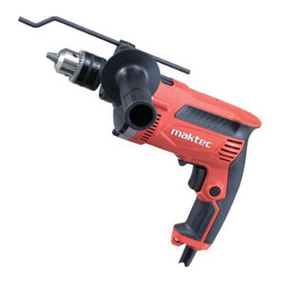
Hammer Drills 16mm (5/8")
C
ONCEPT AND MAIN APPLICATIONS
Models MT814 and MT815 have been developed as the aesthetic
change models of maktec hammer drill MT813, featuring:
Industrial performance and durability at less expense
Tool body ergonomically designed to;
provide comfortable grip and more control.
give maximum power thrust.
The specification difference between MT814 and MT815 is;
MT814: Keyed chuck model
MT815: Keyless chuck model
These models will be also available with:
Plastic carrying case as "K models" (MT814K, MT815K)
Tool box as "KSP models" (MT814KSP, MT815KSP)
S
pecification
Voltage (V)
Current (A)
110
120
220
230
240
Model No.
No load speed: min
= rpm
-1
Impacts per min.: min
-1
Chuck type
Chuck capacity: mm (")
Concrete
Capacities: mm (")
Steel
Wood
Variable speed control by trigger
Reverse switch
Protection against electric shock
Power supply cord: m (ft)
Weight according to
EPTA-Procedure 01/2003*: kg (lbs)
* including Side grip
S
tandard equipment
Chuck key S-13 ................................................ 1 pc (MT814 only)
Key holder 10 ................................................... 1 pc (MT814 only)
Side grip ........................................................... 1 pc
Depth gauge ..................................................... 1 pc
Plastic carrying case ........................................ 1 pc ("K models" only)
Tool box ........................................................... 1 pc ("KSP models" only)
Note: The standard equipment for the tool shown above may vary by country.
O
ptional accessories
TCT drill bits, etc.
All manuals and user guides at all-guides.com
Cycle (Hz)
6.8
50/60
6.2
50/60
3.4
50/60
3.3
50/60
3.1
50/60
MT814
= ipm
Keyed
2.1 (4.6)
Dimensions: mm ( " )
Model No.
MT814
Length (L)
296 (11-5/8)
Width (W)
Height (H)
Continuous Rating (W)
Input
Output
710
420
---
420
710
420
710
420
710
420
MT815
0 - 3,200
0 - 48,000
Keyless
1.5 - 13 (1/16 - 1/2)
16 (5/8)
13 (1/2)
30 (1-3/16)
Yes
Yes
Double insulation
2.0 (6.6)
2.0 (4.4)
PRODUCT
P 1/ 8
L
H
W
(The image above is
MT815.)
MT815
295 (11-5/8)
77 (3)
202 (8)
Max. Output (W)
630
630
630
630
630
Advertisement

Related Manuals for Makita maktec MT814


Summary of Contents for Makita maktec MT814
- Page 1 All manuals and user guides at all-guides.com ECHNICAL INFORMATION PRODUCT P 1/ 8 Model No. MT814, MT815 Description Hammer Drills 16mm (5/8") ONCEPT AND MAIN APPLICATIONS Models MT814 and MT815 have been developed as the aesthetic change models of maktec hammer drill MT813, featuring: Industrial performance and durability at less expense Tool body ergonomically designed to;...
-
Page 2: Necessary Repairing Tools
Portion to lubricate Lubricant Amount Gear housing Gear room where Armature engages with 14 Makita grease N No.1 a. The portion where Ball bearing 6202DDW contacts Spindle b. The portion which is inserted into Plane bearing 8 Molybdenum disulfied of Gear housing complete... -
Page 3: Drill Chuck
All manuals and user guides at all-guides.com P 3/ 8 epair [3] DISASSEMBLY/ASSEMBLY [3]-1. Drill chuck DISASSEMBLING Drill chuck can be removed as illustrated in Fig. 2 when Drill chuck is not out of order. Fig. 2 1. Fit the flats of Spindle to the notch of 1R139 and then hold 1R139 in vise. 2. - Page 4 All manuals and user guides at all-guides.com P 4/ 8 epair [3] DISASSEMBLY/ASSEMBLY [3]-2. Armature DISASSEMBLING (1) Remove Armature from the machine as illustrated in Fig. 3. Fig. 3 1. Remove Handle cover complete 2. Separate Gear housing and Gear 3.
- Page 5 All manuals and user guides at all-guides.com P 5/ 8 epair [3] DISASSEMBLY/ASSEMBLY [3]-3. Helical gear 37, Ball bearing 6202DDW DISASSEMBLING (1) Remove Drill chuck as illustrated in Fig. 2. (2) Separating Gear housing, remove Pin 4, Steel ball 3.5 and Rind spring 12 from Spindle as illustrated in Fig. 5. Fig.
- Page 6 All manuals and user guides at all-guides.com P 6/ 8 epair [3] DISASSEMBLY/ASSEMBLY [3]-3. Helical gear 37, Ball bearing 6202DDW (cont.) ASSEMBLING (4) Remove Ball bearing 6202DDW as illustrated in Fig. 7. Use the removed Spindle as a jig. Fig. 7 2.
-
Page 7: Circuit Diagram
All manuals and user guides at all-guides.com P 7/ 8 ircuit diagram Fig. D-1 Color index of lead wires' sheath Black Orange Blue Brown Purple Brush holder on the opposite of Switch Field viewed from Commutator side Brush holder near Switch Switch Noise suppressor (if used) -
Page 8: Wiring Diagram
All manuals and user guides at all-guides.com P 8/ 8 iring diagram Fig. D-2 Wiring of Field lead wires Left coil Route Field lead wires (black, white) of Left coil between Rib A and Rib B of Motor housing. Right coil (Handle cover side) Route Field lead wires (black, red) Rib A...