Advertisement
T
ECHNICAL INFORMATION
Model No.
Description
C
ONCEPT AND MAIN APPLICATIONS
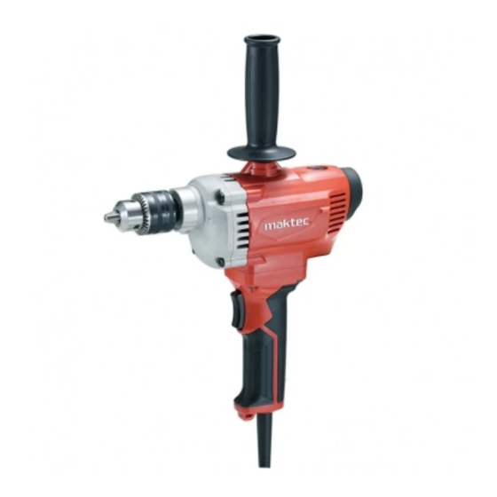
MT622 has been developed as a cost-effective maktec 13mm Drill for emerging countries.
Its features are as follows:
• Without Variable speed control switch
• With Rotation reversing facility
S
pecification
Voltage (V)
110
120
220
230
240
Specification
No load speed: min
¹= rpm
ˉ
Drill chuck type
Chuck capacity: mm (")
Capacities: mm (")
Rotation reversing facility
Variable speed control by trigger
Soft grip
Protection against electric shock
Power supply cord: m (ft)
Weight according to
EPTA-Procedure 01/2003*: kg (lbs)
* With Top grip
S
tandard equipment
Top grip .........................................................1
Chuck key .....................................................1
Key holder .....................................................1
Note: The standard equipment may vary by country.
O
ptional accessories
D-handle
MT622
13mm Drill
Current (A)
Cycle (Hz)
7.2
50/60
6.6
50/60
3.6
50/60
3.5
50/60
3.3
50/60
Model
1.5 - 13 (1/16 - 1/2)
Steel
Wood
Yes (Rocker switch)
Double insulation
Continuous Rating (W)
Input
750
---
750
750
750
MT622
600
Keyed
13 (1/2)
36 (1-7/16)
No
Yes
2.0 (6.6)
2.7 (6.0)
OFFICIAL USE
for ASC & Sales Shop
PRODUCT
P 1/ 8
L
H
W
Dimensions: mm (")
Length (L)
267 (10-1/2)
Width (W)
86 (3-3/8)
Height (H)
396 (15-5/8)
Max. Output (W)
Output
350
550
350
550
350
550
350
550
350
550
Advertisement
Table of Contents

Summary of Contents for Makita Maktec MT622
- Page 1 OFFICIAL USE for ASC & Sales Shop ECHNICAL INFORMATION PRODUCT P 1/ 8 Model No. MT622 Description 13mm Drill ONCEPT AND MAIN APPLICATIONS MT622 has been developed as a cost-effective maktec 13mm Drill for emerging countries. Its features are as follows: •...
-
Page 2: Necessary Repairing Tools
Bearing retainer 23-36 781024-2 Wrench 43 removing damaged Drill chuck S-13 [2] LUBRICATION Apply Makita grease FA No.2 to the following portions designated with the black triangle to protect parts and product from unusual abrasion. Item No. Description Portion to lubricate Amount 5g approx. -
Page 3: Drill Chuck
P 3/ 8 epair [3] DISASSEMBLY/ASSEMBLY [3]-2. Drill chuck DISASSEMBLING 1R139 Drill chuck S-13 (1) Remove Drill chuck S-13 from the machine as drawn in Fig. 3 or Fig. 3A. Fig. 3 wrench 1. Secure a hex wrench in Drill chuck firmly. 2. - Page 4 P 4/ 8 epair [3] DISASSEMBLY/ASSEMBLY [3]-3. Spindle and Gear section (cont.) DISASSEMBLING (1) Remove Drill chuck from the machine as drawn in Fig. 3/ 3A. (2) Remove Gear housing as drawn in Fig. 5. (3) Disassemble Gears from Gear housing complete as drawn in Fig. 6. Fig.
- Page 5 P 5/ 8 epair [3] DISASSEMBLY/ASSEMBLY [3]-3. Spindle and Gear section (cont.) ASSEMBLING (1) Assemble Gear section by reversing the disassembly procedure. (Fig. 7) Fig. 7 1. Assemble Ball bearing 626ZZ 2. Pressfit Ball bearing 6202DDW 3. Insert Ring 15 to Spindle. to Gear housing complete.
-
Page 6: Circuit Diagram
P 6/ 8 ircuit diagram Fig. D-1 Circuit without Radio interference suppression Circuit of Switch [View from Commutator side] Non-insulated connector Terminal block Closed end splice Forward mode: is used for some conduct 2 - 6, 3 - 5 Field countries. -
Page 7: Wiring Diagram
P 7/ 8 iring diagram Fig. D-2 Setting and Wiring of Field Lead wire Assemble Field to Motor housing Field lead wires have to be guided as follows. while facing the wire connected 1. Guide out Field lead wires while tightening portion to Cap side. - Page 8 P 8/ 8 iring diagram Fig. D-3 Wiring in Switch handle L with Radio interference suppression Wiring through Line filter Pass Field lead wires (orange, purple) through Line filter as drawn below. And put it to the place as drawn right. One hole type Line filter Two holes type...


Need help?
Do you have a question about the Maktec MT622 and is the answer not in the manual?
Questions and answers