Table of Contents
Advertisement
Quick Links
GETTING STARTED GUIDE
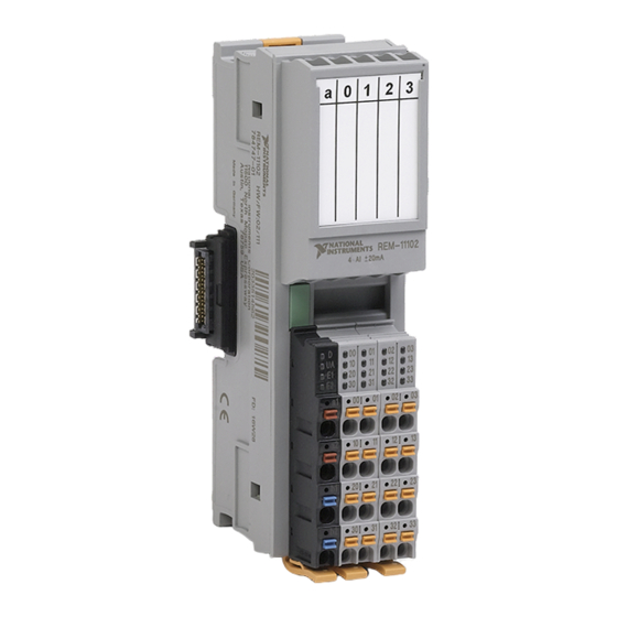
NI REM-11102
Current Input Module for Remote I/O
This document explains how to connect to the REM-11102.
Note
The guidelines in this document are specific to the REM-11102. The other
components in the system might not meet the same safety ratings. Refer to the
documentation for each component in the system to determine the safety and EMC
ratings for the entire system.
Caution
document. Product misuse can result in a hazard. You can compromise the safety
protection built into the product if the product is damaged in any way. If the product
is damaged, return it to NI for repair.
Do not operate the REM-11102 in a manner not specified in this
Advertisement
Table of Contents

Related Manuals for National Instruments REM-11102


Summary of Contents for National Instruments REM-11102
- Page 1 This document explains how to connect to the REM-11102. Note The guidelines in this document are specific to the REM-11102. The other components in the system might not meet the same safety ratings. Refer to the documentation for each component in the system to determine the safety and EMC ratings for the entire system.
-
Page 2: Electromagnetic Compatibility Guidelines
Furthermore, any changes or modifications to the product not expressly approved by National Instruments could void your authority to operate it under your local regulatory rules. Preparing the Environment Ensure that the environment in which you are using the REM-11102 meets the following specifications. Operating temperature -25 °C to 60 °C... -
Page 3: Verifying The Kit Contents
Refer to the device datasheet on ni.com/manuals for complete specifications. Verifying the Kit Contents Verify that the following items are included in the REM-11102 kit. Figure 1. REM-11102 Kit Contents 1. NI REM-11102 3. Supply voltage connector 2. Bus connector 4. - Page 4 White Bus coupler, power module Installing Bus Connectors What to Use • Bus connector • DIN rail What to Do Complete the following steps to install bus connectors on the DIN rail. 4 | ni.com | REM-11102 Getting Started Guide...
-
Page 5: Installing The Module
Repeat Steps 2 and 3 for additional bus connectors. Installing the Module What to Use • REM-11102 • Mounted bus connector What to Do Complete the following steps to install the REM-11102 on the DIN rail. REM-11102 Getting Started Guide | © National Instruments | 5... - Page 6 Note Verify that the bus connector socket aligns with the socket on the underside of the module. Press the REM-11102 directly onto the bus connector and DIN rail until it clicks into place. Caution Tilting the module when mounting it on the DIN rail will damage the contacts.
- Page 7 Negative voltage connection for channel 0 to 3 20 to 23 0 to U 24 V sensor supply for channel 0 to 3 30 to 33 Reference potential of sensor supply REM-11102 Getting Started Guide | © National Instruments | 7...
- Page 8 Green Flashing Data is invalid or unavailable. The REM-11102 cannot communicate with the Green/Yellow Flashing connected devices. The REM-11102 did not detect a valid cycle after power- Solid Yellow Flashing The REM-11102 is not part of the configuration. Solid The REM-11102 has lost connection to the Bus Coupler.
- Page 9 Connecting the REM-11102 Figure 4. REM-11102 Current Measurement Connection Sensor AI+ (0:3) AI– (0:3) 24 VDC (0:3) 24 VDC – REM-11102 and GND are optional, sensor-dependent connections. REM-11102 Getting Started Guide | © National Instruments | 9...
-
Page 10: Connection Guidelines
• NI recommends using the NI Remote I/O Shield Set for optimal shield connection. • Make sure that devices you connect to the REM-11102 are compatible with the module specifications. • Push the wire into the terminal when using a solid wire or a stranded wire with a ferrule. -
Page 11: Removing Components
Removing Components Removing Spring Terminal Blocks Complete the following steps to remove a spring-terminal block from the REM-11102. Press the locking latch to release the spring-terminal block. Tilt the block toward the center of the module. Remove the connector from the module. - Page 12 If you want to remove a bus connector in the middle of the system, you must remove any modules or bus connectors following the desired connector or slide them along the DIN rail at least 15.0 mm (0.60 in.). 12 | ni.com | REM-11102 Getting Started Guide...
-
Page 13: Where To Go Next
78759-3504. NI also has offices located around the world. For telephone support in the United States, create your service request at ni.com/support or dial 1 866 ASK MYNI (275 6964). For REM-11102 Getting Started Guide | © National Instruments | 13... - Page 14 CONTAINED HEREIN AND SHALL NOT BE LIABLE FOR ANY ERRORS. U.S. Government Customers: The data contained in this manual was developed at private expense and is subject to the applicable limited rights and restricted data rights as set forth in FAR 52.227-14, DFAR 252.227-7014, and DFAR 252.227-7015. © 2016 National Instruments. All rights reserved. 376556A-01 Oct16...
Need help?
Do you have a question about the REM-11102 and is the answer not in the manual?
Questions and answers