Advertisement
Quick Links
R
333 Bayview Avenue, Amityville, New York 11701
For Sales and Repairs, (800) 645-9445
For Technical Service, (800) 645-9440 or visit us at
http://tech.napcosecurity.com/
(Note: Technical Service is for security professionals only)
Publicly traded on NASDAQ
Symbol: NSSC
© NAPCO 2020
™
The StarLink
Signal Strength Tester allows you to perform a
site survey test of the premises to find the optimum installa-
tion locations for your StarLink
tor. Four different models are available, the SLE-LTEV-SS
and SLE-LTEV-SS-CF (LTE Verizon cellular network);
SLE-LTEA-SS and SLE-LTEA-SS-CF (LTE AT&T cellular
network).
For more information, visit
load PDF files of all needed documentation.
SPECIFICATIONS
Battery Pack: Standard USB 5V 10000mAh
Note: Unit must be off when charging battery.
Battery Life Indicator: Four (4) small blue LEDs display
the real-time percentage of remaining battery power
(recharge when one LED is lit)
Typical Battery Life: About 23 hours of continuous use
after a full charge
Battery Charger: 5V/2A wall plug adapter
Dimensions (W x H x D): 8 x 5-
3.8cm)
Operating Temperature: 0° - 49°C (32° - 120°F)
Humidity: Maximum 93% Non-Condensing
Indoor / dry location use only
OPERATION
1. Power on (press "–" on the rocker switch).
2. Wait 1-2 minutes for unit to enter "Standby Mode" with
LEDs indicating:
Top Red LED flashes, then turns off
Right Green LED flashes
Yellow LED momentary flashes
3. Place unit in potential installation location.
4. Wait 2 minutes.
5. Count the right Green LED flashes (acceptable power
level is greater than or equal to 2 blinks).
If moving location, go to step 4.
If the top Red LED blinks or turns on solid, you MUST
go to step 2. If step 2 LED flashes do not occur, signal
is likely too weak (try a different location).
Power off when not in use and when charging. After
powering off, wait at least 30 seconds before power-
ing on.
LED DESCRIPTIONS
There are five (5) LEDs on the front of the unit:
Green RF Signal Strength LED: Every 30 seconds, the
StarLink communicator receiver turns on and listens to the
cell tower. Depending on the signal strength detected, this
LED will blink from 1 to 5 times at a constant rate (with a
short delay between blink cycles) to provide a signal strength
indicator that is updated constantly and is always displayed.
Acceptable power level is greater than or equal to 2
blinks.
StarLink
Operating Instructions
™
alarm capture communica-
tech.napcosecurity.com
to down-
29
/
x 1½" (20.3 x 13.9 x
64
Communicator
™
Signal Strength Tester
IMPORTANT: The green Signal Strength LED will pro-
vide a valid reading only when the red Diagnostic LED is
NOT lit (blinking or solid) and the yellow Status LED is not
on solid.
Red Diagnostic LED: Labeled " D7" on the PCB, this LED
will light and flash when the unit is powered (see OPERA-
TION, above). One blink indicates a weak or non-existent
signal from the network (green RF Signal Strength LED is
off).
Green Power LED:
Note: To maximize battery life, press the " O" on the side
switch to power off when not in use.
Yellow Status LED: When the unit is first powered, this
LED will turn on solid for a few seconds, flash, remain on sol-
id again and then turn off. After a connection to the cell tower
is made and the unit is in a normal standby condition, it will
then blink momentarily every 10 seconds.
Red Trouble LED: This LED will blink as follows:
1 Blink: Low Aux Power input voltage
2 Blinks: Battery trouble
3 Blinks: Alarm report Failed to Communicate
4 Blinks: RF trouble (antenna connection or cellular
registration)
5 Blinks: Network trouble (signal unable to reach the
SLE Control Center)
6 Blinks: Unit disabled (reporting or control panel
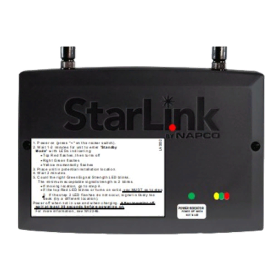
1. P ow e r on (p r es s " – " on t h e r oc ke r s wit ch ) .
2. W ai t 1 -2 mi nu te s f or uni t t o e nt er "St a n db y
M o d e" w i th LE Ds i n d i ca t i n g:
3. Pl ac e u ni t i n p ot e nt ia l i ns t all at io n lo c ati o n.
4. W ai t 2 mi n ut e s.
5. C o un t th e r ig h t Gr e e n Si g n al St re n gt h L ED bl in ks .
T he mi ni m u m ac ce p ta bl e si g na l s t re n gt h is 2 bli nk s.
Signal Strength Tester
Pow e r o ff w he n n ot i n u se a n d w he n c ha r gi ng . A ft e r po w er in g o ff ,
wa i t a t le a s t 3 0 s ec o n d s b e f or e p o w er i n g o n.
F or m or e in f or m at io n , se e WI 2 3 46 .
When lit, the unit is powered on.
Red Diagnostic
Green RF
Green
Signal Strength
Power
Yellow
Red Trouble
Status
Front LED Descriptions
T op R e d fl as h es , t h e n tu r ns o ff
Rig h t G re e n fl as he s
Yell o w m o me n ta ril y fl as h es
If m o vi ng l oc at io n, go t o st e p 4 .
If t he t o p Re d L ED bl in ks o r t u rn s o n so li d, y ou MU ST go t o st e p
SLE-LTEV -SS
2. If t h e s t ep 2 LED f la s he s d o n ot o cc u r, si g na l i s lik el y to o
we ak (t ry a dif f er e nt l oc at io n ).
PO WER INDICATO R
P OWE R OFF WHE N
NOT I N US E
WI2346ALF 6/20
Advertisement

Related Manuals for NAPCO StarLink SLE-LTEV-SS


Summary of Contents for NAPCO StarLink SLE-LTEV-SS
- Page 1 P OWE R OFF WHE N NOT I N US E Publicly traded on NASDAQ Symbol: NSSC WI2346ALF 6/20 © NAPCO 2020 ™ The StarLink Signal Strength Tester allows you to perform a IMPORTANT: The green Signal Strength LED will pro-...
- Page 2 All rights reserved. All trademarks, service marks, and product or service names described in this manual are for identification purposes only and may be trademarks or registered trade- marks of their respective owners. The absence of a name or logo in this document does not constitute a waiver of any and all intellectual property rights that NAPCO Security Technologies, Inc. has...