Table of Contents
Advertisement
Advertisement
Table of Contents

Related Manuals for HIKVISION HWN-2100H Series


Summary of Contents for HIKVISION HWN-2100H Series
- Page 1 Network Video Recorder User Manual...
- Page 2 Any and all information, including, among others, wordings, pictures, graphs are the properties of Hangzhou Hikvision Digital Technology Co., Ltd. or its subsidiaries (hereinafter referred to be “Hikvision”). This user manual (hereinafter referred to be “the Manual”) cannot be reproduced, changed, translated, or distributed, partially or wholly, by any means, without the prior written permission of Hikvision.
- Page 3 Network Video Recorder User Manual Regulatory Information FCC Information Please take attention that changes or modification not expressly approved by the party responsible for compliance could void the user’s authority to operate the equipment. FCC compliance: This equipment has been tested and found to comply with the limits for a Class A digital device, pursuant to part 15 of the FCC Rules.
- Page 4 Network Video Recorder User Manual Safety Instructions Proper configuration of all passwords and other security settings is the responsibility of the installer and/or end-user. In the use of the product, you must be in strict compliance with the electrical safety regulations of the nation and region.
- Page 5 Network Video Recorder User Manual Applicable Models This manual is applicable to the models listed in the following table. Series Model HWN-2104H HWN-2100H HWN-2108H HWN-2104H-4P HWN2100H-P HWN-2108H-8P HWN-2104MH HWN-2100MH HWN-2108MH HWN-2104MH-4P HWN-2100MH-P HWN-2108MH-8P Symbol Conventions The symbols that may be found in this document are defined as follows. Symbol Description Provides additional information to emphasize or supplement...
- Page 6 Network Video Recorder User Manual Product Key Features General Connectable to network cameras, network dome and encoders. Connectable to the third-party network cameras via HIK, ONVIF, private RTSP protocols. Connectable to the smart IP cameras. PAL/NTSC adaptive video inputs. ...
- Page 7 Network Video Recorder User Manual Continuous and event video recording parameters. Multiple recording types: manual, continuous, alarm, motion, motion | alarm, motion & alarm. 8 recording time periods with separated recording types each day. Pre-record and post-record for alarm, motion detection for recording, and pre- record time for schedule and manual recording.
- Page 8 Network Video Recorder User Manual Supports line crossing detection and intrusion detection. VCA alarm message push via iVMS-4500 mobile client software. Other Local Functions Three-level user management; admin user is allowed to create many operating accounts and define their operating permission, which includes the limit to access any channel.
- Page 9 Network Video Recorder User Manual Remote JPEG capture. Two-way audio and voice broadcasting. Embedded WEB server. Upgrade by FTP server. Development Scalability: SDK for Windows and Linux system. Source code of application software for demo. ...
-
Page 10: Table Of Contents
Network Video Recorder User Manual TABLE OF CONTENTS Chapter 1 Introduction ..................... 13 Front Panel ....................13 USB Mouse Operation ................13 Rear Panel ....................14 Chapter 2 Getting Started..................... 17 Device Startup and Activation ..............17 Starting Up and Shutting Down the NVR .......... 17 Activating Your Device .............. - Page 11 Network Video Recorder User Manual Customizing Linear Scan Limit ............51 Calling Linear Scan ................52 One-touch Park ................. 52 PTZ Control Panel ................54 Chapter 5 Recording Settings .................. 56 Configuring Parameters ................56 Configuring Recording Schedule ..............58 Configuring Motion Detection Recording ..........
- Page 12 Network Video Recorder User Manual Managing Backup Devices ................. 93 Chapter 8 Alarm Settings ..................94 Setting Motion Detection Alarm ..............94 Setting Sensor Alarms ................96 Detecting Video Loss Alarm ............... 98 Detecting Video Tampering Alarm ............. 99 Line Crossing Detection Alarm ..............101 Intrusion Detection Alarm................
- Page 13 Network Video Recorder User Manual Viewing System Information ..............132 Searching & Export Log Files ..............132 Importing/Exporting Configuration Files ..........135 Upgrading System .................. 135 Upgrading by Local Backup Device ..........135 Upgrading by FTP ................136 Restoring Default Settings ..............137 Chapter 13 Others ....................
-
Page 14: Chapter 1 Introduction
Network Video Recorder User Manual Chapter 1 Introduction Front Panel HWN2100H-P Series HWN-2100MH-P Series Description of Front Panel No. Icon Description Indicator turns red when NVR is powered up. Indicator lights in red when data is being read from or written to HDD. -
Page 15: Rear Panel
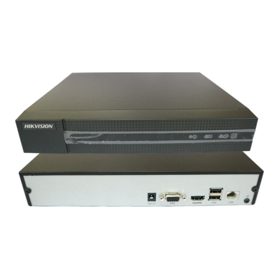
Network Video Recorder User Manual The mouse should automatically be detected. If in a rare case that the mouse is not detected, the possible reason may be that the two devices are not compatible, please refer to the recommended the device list from your provider. The operation of the mouse: Description of the Mouse Control Name... - Page 16 Network Video Recorder User Manual HWN-2100H and HWN-2100MH Series HWN-2100H Rear Panel HWN-2100MH Rear Panel Description of Rear Panel Item Description Power Supply 12 VDC power supply. VGA Interface DB9 connector for VGA output. Display local video output and menu. HDMI Interface HDMI video output connector.
- Page 17 Network Video Recorder User Manual HWN2100H-P and HWN-2100MH-P Series HWN2100H-P Rear Panel HWN-2100MH-P Rear Panel Description of Rear Panel Item Description Power Supply 12 VDC power supply. VGA Interface DB9 connector for VGA output. Display local video output and menu. HDMI Interface HDMI video output connector.
-
Page 18: Chapter 2 Getting Started
Network Video Recorder User Manual Chapter 2 Getting Started Device Startup and Activation Starting Up and Shutting Down the NVR Purpose: Proper startup and shutdown procedures are crucial to expanding the life of the NVR. Before you start: Check that the voltage of the extra power supply is the same with the NVR’s requirement, and the ground connection is working properly. -
Page 19: Activating Your Device
Network Video Recorder User Manual Shutdown Attention Rebooting the NVR In the Shutdown menu, you can also reboot the NVR. Go to Menu > Shutdown. Click Logout to lock the NVR or Reboot to reboot the NVR. Activating Your Device Purpose: For the first-time access, you need to activate the device by setting an admin password. - Page 20 Network Video Recorder User Manual When the device is activated, the system pops up the message box to remind you to remember the password. And you can click Yes to continue to export the GUID file for the future password resetting. Export GUID File Remind Insert the U-flash disk to your device, and export the GUID file to the U-flash disk in the Reset Password interface.
-
Page 21: Using The Unlock Pattern For Login
Network Video Recorder User Manual Warning Using the Unlock Pattern for Login You can configure the unlock pattern for device login. Configuring the Unlock Pattern After the device is activated, you can enter the following interface to configure the device unlock pattern. Set Unlock Pattern Step 1 Use the mouse to draw a pattern among the 9 dots on the screen. - Page 22 Network Video Recorder User Manual Draw the Pattern Connect at least 4 dots to draw the pattern. Each dot can be connected for once only. Step 2 Draw the same pattern again to confirm it. When the two patterns match, the pattern is configured successfully.
- Page 23 Network Video Recorder User Manual Re-set the Pattern Logging in via Unlock Pattern Only the admin user has the permission to unlock the device. Please configure the pattern first before unlocking. Please refer to Configuring the Unlock Pattern: Right click the mouse on the screen and select the menu to enter the interface as shown in Figure 2.8.
-
Page 24: Login And Logout
Network Video Recorder User Manual Normal Login Dialog Box Login and Logout User Login Purpose: If NVR has logged out, you must login the device before operating the menu and other functions. Select User Name in the dropdown list. Login Interface Input password. -
Page 25: Resetting Your Password
Network Video Recorder User Manual After logging out, the monitor turns to the live view mode and if you want to do some operation, you need to enter user name and password tog in again. Go to Menu > Shutdown. Logout Click Logout. -
Page 26: Using The Wizard For Basic Configuration
Network Video Recorder User Manual Select the GUID file from the U-flash disk and click Import to import the file to the device. If you have imported the wrong GUID file for 7 times, you will be not allowed to reset the password for 30 minutes. - Page 27 Network Video Recorder User Manual Start Wizard Interface Click Next to enter the IP Camera Management interface. Automatically Add Cameras (for Non-PoE Models) For non-PoE devices, you can quickly add one or more IP cameras which are searched within the same network and have the same user name and password with the device.
- Page 28 Network Video Recorder User Manual 1) Click Add All. The device starts to automatically search and add the matched cameras. 2) Click OK when the cameras are added. Manually Add Cameras 1) Click Search to search the online IP cameras within the same network. 2) Click Add to add the cameras which have the same user name and password with the device.
-
Page 29: Adding And Connecting The Ip Cameras
Network Video Recorder User Manual Adding and Connecting the IP Cameras Activating the IP Camera Purpose: Before adding the camera, make sure the IP camera to be added is in active status. Select Add IP Camera from the right-click menu in live view mode or Go to Menu> Camera>... -
Page 30: Adding The Online Ip Cameras
Network Video Recorder User Manual Set New Password Create New Password: If the admin password is not used, you must create the new password for the camera and confirm it. We highly recommend you create a strong password of your own choosing (Using a minimum of 8 characters, including at least three of the following categories: upper case letters, lower case letters, numbers, and special characters.) in order to increase the security of your product. - Page 31 Network Video Recorder User Manual Adding IP Camera Interface The online cameras with same network segment will be detected and displayed in the camera list. Select the IP camera from the list and click the button to add the camera. Or you can click One-touch Adding to add all cameras (with the same login password) from the list.
- Page 32 Network Video Recorder User Manual Custom Adding IP Camera Interface You can edit the IP address, protocol, management port, and other information of the IP camera to be added. If the IP camera to add has not been actiavated, you can activate it from the IP camera list on the camera management interface.
-
Page 33: Editing The Connected Ip Cameras And Configuring Customized Protocols
Network Video Recorder User Manual For the added IP cameras, the Security status shows the security level of the password of camera: strong password, weak password and risk password. Security Level of IP Camera’s Password Enabling the Password of IP Camera Visible For the admin login user account, you can check Show Password of IP Camera to enable the show the passwords of the successfully added IP cameras in the list. - Page 34 Network Video Recorder User Manual Edit the Parameters Channel Port: If the connected device is an encoding device with multiple channels, you can choose the channel to connect by selecting the channel port No. in the dropdown list. Click OK to save the settings and exit the editing interface. Editing the Advanced Parameters Drag the horizontal scroll bar to the right side and click the icon.
- Page 35 Network Video Recorder User Manual Password Configuration of the Camera Click OK to save the settings and exit the interface. Configuring the Customized Protocols Purpose: To connect the network cameras which are not configured with the standard protocols, you can configure the customized protocols for them. Click Protocol in the custom adding IP camera interface to enter the protocol management interface.
-
Page 36: Editing Ip Cameras Connected To The Poe Interfaces
Network Video Recorder User Manual Before customizing the protocol for the network camera, you have to contact the manufacturer of the network camera to consult the URL (uniform resource locator) for getting main stream and sub-stream. The format of the URL is: [Type]://[IP Address of the network camera]:[Port]/[Path]. Example: rtsp://192.168.1.55:554/ch1/main/av_stream. - Page 37 Network Video Recorder User Manual The PoE interfaces enables the NVR system to pass electrical power safely, along with data, on Ethernet cabling to the connected network cameras. Up to 4 network cameras can be connected to /4P models, and 8 network cameras to /8P models.
- Page 38 Network Video Recorder User Manual Edit IP Camera Interface - Plug-and-Play Manual: You can disable the PoE interface by selecting the manual while the current channel can be used as a normal channel and the parameters can also be edited. Input the IP address, the user name and password of administrator manually, and click OK to add the IP camera.
-
Page 39: Chapter 3 Live View
Network Video Recorder User Manual Chapter 3 Live View Live View displays the video image getting from each camera in real time. Live View Status Icons In the live view mode, there are status icons at the upper-right of the screen for each channel, showing the status of the record and alarm in the channel, so that you can know whether the channel is recorded, or whether there are alarms occur as soon as possible. -
Page 40: Quick Setting Toolbar In Live View Mode
Network Video Recorder User Manual Mouse Operation in Live View Name Description Common Menu Quick access to the sub-menus which you frequently visit. Enter the main menu of the system by right clicking the Menu mouse. Switch to the single full screen by choosing channel number Single Screen from the dropdown list. - Page 41 Network Video Recorder User Manual Quick Setting Toolbar Description of Quick Setting Toolbar Icons Icon Description Icon Description Icon Description Enable/Disable Instant Mute/Audio Manual Record Playback Image PTZ Control Digital Zoom Settings Live View Face Detection Information Strategy Main/Sub- Close Stream Instant Playback only shows the record in last five minutes.
-
Page 42: Adjusting Live View Settings
Network Video Recorder User Manual Image Settings- Customize Live View Strategy can be selected to set strategy, including Real-time, Balanced, Fluency. Live View Strategy Move the mouse onto the icon to show the real-time stream information, including the frame rate, bitrate, resolution and stream type. Information Adjusting Live View Settings Purpose:... - Page 43 Network Video Recorder User Manual Go to Menu > Configuration > Live View. Live View-General The settings available in this menu include: Video Output Interface: Designates the output to configure the settings for, and only VGA/ HDMI is selectable by default. ...
-
Page 44: Channel-Zero Encoding
Network Video Recorder User Manual 1) Select a View mode in . Up to 36-screen display is supported for 32-ch NVR. 2) Select the small window, and double-click on the channel number to display the channel on the window. 3) If you do not want the camera to be displayed on the live view interface, click the corresponding to stop it. - Page 45 Network Video Recorder User Manual Configure the Frame Rate, Max. Bitrate Mode and Max. Bitrate. After you set the Channel-Zero encoding, you can get a view in the remote client or web browser of 16 channels in one screen.
-
Page 46: Chapter 4 Ptz Controls
Network Video Recorder User Manual Chapter 4 PTZ Controls Configuring PTZ Settings Purpose: Follow the procedure to set the parameters for PTZ. The configuring of the PTZ parameters should be done before you control the PTZ camera. Go to Menu > Camera > PTZ. PTZ Settings Click PTZ Parameters to set the PTZ parameters. - Page 47 Network Video Recorder User Manual Choose the camera for PTZ setting in the Camera dropdown list. Enter the parameters of the PTZ camera. All the parameters should be exactly the same as the PTZ camera parameters. Click Apply to save the settings.
-
Page 48: Setting Ptz Presets, Patrols & Patterns
Network Video Recorder User Manual Setting PTZ Presets, Patrols & Patterns Before you start: Please make sure that the presets, patrols and patterns should be supported by PTZ protocols. Customizing Presets Purpose: Follow the steps to set the Preset location which you want the PTZ camera to point to when an event takes place. -
Page 49: Customizing Patrols
Network Video Recorder User Manual Or press the PTZ button on the front panel or click the PTZ Control icon the quick setting bar, or select the PTZ option in the right-click menu to show the PTZ control panel. Choose Camera in the dropdown list. Click the button to show the general settings of the PTZ control. -
Page 50: Calling Patrols
Network Video Recorder User Manual Select patrol No. in the drop-down list of patrol. Click Set to add key points for the patrol. Key point Configuration Configure key point parameters, such as the key point No., duration of staying for one key point and speed of patrol. -
Page 51: Customizing Patterns
Network Video Recorder User Manual Select a patrol in the dropdown list and click the Call Patrol button to call it. You can click the Stop Patrol button to stop calling it. Customizing Patterns Purpose: Patterns can be set by recording the movement of the PTZ. You can call the pattern to make the PTZ movement according to the predefined path. -
Page 52: Customizing Linear Scan Limit
Network Video Recorder User Manual PTZ Panel - General Click Call Pattern to call it. Click Stop Pattern to stop calling it. Customizing Linear Scan Limit Purpose: The Linear Scan can be enabled to trigger the scan in the horizantal direction in the predefined range. -
Page 53: Calling Linear Scan
180º. Calling Linear Scan Before operating this function, make sure the connected camera supports the linear scan and is in HIKVISION protocol. Purpose: Follow the procedure to call the linear scan in the predefined scan range. - Page 54 Network Video Recorder User Manual For some certain model of the speed dome, it can be configured to start a predefined park action (scan, preset, patrol and etc.) automatically after a period of inactivity (park time). Click PTZ in the lower-right corner of the PTZ setting interface; Or press the PTZ button on the front panel or click the PTZ Control icon the quick setting bar to enter the PTZ setting menu in live view mode.
-
Page 55: Ptz Control Panel
Network Video Recorder User Manual PTZ Control Panel To enter the PTZ control panel, there are two ways supported. OPTION 1: In the PTZ settings interface, click PTZ on the lower-right corner which is next to the Back button. OPTION 2: In the Live View mode, you can press the PTZ Control button on the front panel or on the remote control, or choose the PTZ Control icon , or select the PTZ option in... - Page 56 Network Video Recorder User Manual Icon Icon Description Icon Description Description interface control interface interface Start pattern / Previous item Next item patrol Stop the patrol Minimize pattern Exit windows movement...
-
Page 57: Chapter 5 Recording Settings
Network Video Recorder User Manual Chapter 5 Recording Settings Configuring Parameters Purpose: By configuring the parameters you can define the parameters which affect the image quality, such as the transmission stream type, the resolution and so on. Before you start: Make sure that the HDD has already been installed. - Page 58 Network Video Recorder User Manual configurable. Enabling it helps to ensure the high video quality with a lowered bitrate. The function is only available for IP cameras which support H.264+ stream. 2) Click the More Settings button to set the advanced parameters for recording and then click OK button to finish editing.
-
Page 59: Configuring Recording Schedule
Network Video Recorder User Manual files in the IP camera when the network is disconnected, and synchronize the files to the NVR when the network is resumed. The redundant record is to decide whether you want the camera to save the recording files in the redundant HDD. - Page 60 Network Video Recorder User Manual Record Schedule Different recording types are marked in different color icons. Continuous: scheduled recording. Event: recording triggered by all event triggered alarm. Motion: recording triggered by motion detection. Alarm: recording triggered by alarm. ...
- Page 61 Network Video Recorder User Manual To schedule an all-day recording, check the checkbox after the All Day item. Edit Schedule To arrange other schedule, leave the All Day checkbox blank and set the Start/End time. Up to 8 periods can be configured for each day. And the time periods cannot be overlapped each other.
-
Page 62: Configuring Motion Detection Recording
Network Video Recorder User Manual Draw the Schedule Click Apply to validate the settings. (Optional) If the settings can also be used to other channels, click Copy, and then choose the channel to which you want to copy. Click Apply to save the settings. Configuring Motion Detection Recording Purpose: Follow the steps to set the motion detection parameters. - Page 63 Network Video Recorder User Manual Configure Motion Detection Choose camera you want to configure. 2) Check the checkbox after Enable Motion Detection. 3) Drag and draw the area for motion detection by mouse. If you want to set the motion detection for all the area shot by the camera, click Full Screen. To clear the motion detection area, click Clear.
-
Page 64: Configuring Alarm Triggered Recording
Network Video Recorder User Manual Edit the Motion Detection Record Schedule. For the detailed information of schedule configuration, see Chapter 5.2 Configuring Recording Schedule. Configuring Alarm Triggered Recording Purpose: Follow the procedure to configure alarm triggered recording. Go to Menu > Configuration > Alarm. Alarm Settings Click Alarm Input tab and set the alarm parameters. -
Page 65: Configuring Vca Event Recording
Network Video Recorder User Manual Alarm Settings 1) Choose the alarm triggered recording channel. 2) Check the checkbox to select channel. 3) Click Apply to save settings. 4) Click OK to back to the upper level menu. Repeat the above steps to configure other alarm input parameters. If the settings can also be applied to other alarm inputs, click Copy and choose the alarm input number. - Page 66 Network Video Recorder User Manual Go to Menu > Camera > VCA. VCA Settings Configure the detection rules for the line crossing detection or intrusion detection. Click the icon to configure the alarm linkage actions for the VCA events. Select Trigger Channel tab and select one or more channels which will start to record when VCA alarm is triggered.
-
Page 67: Manual Recording
Network Video Recorder User Manual Manual Recording Purpose: Follow the steps to set parameters for the manual record. Using manual record, you need to manually cancel the record. The manual recording is prior to the scheduled recording. Go to Menu > Manual. Or press the REC/SHOT button on the front panel. -
Page 68: Configuring Redundant Recording
Network Video Recorder User Manual Holiday Settings Enable Edit Holiday schedule. 1) Click to enter the Edit interface. Edit Holiday Settings 2) Check the checkbox after Enable Holiday. 3) Select Mode from the dropdown list. 4) There are three different modes for the date format to configure holiday schedule. - Page 69 Network Video Recorder User Manual Go to Menu > HDD. HDD General Select the HDD and click to enter the Local HDD Settings interface. 7) Set the HDD property to Redundancy. HDD General-Editing Click Apply to save the settings. Click OK to back to the upper level menu. You must set the Storage mode in the HDD advanced settings to Group before you set the HDD property to Redundant.
-
Page 70: Files Protection
Network Video Recorder User Manual Record Parameters 3) Check Redundant Record. 4) Click OK to save settings and back to the upper level menu. Repeat the above steps for configuring other channels. Files Protection Purpose: You can lock the recording files or set the HDD property to Read-only to protect the record files from being overwritten. - Page 71 Network Video Recorder User Manual During playback, click the button to lock the current recording file. In the multi-channel playback mde, clicking the button will lock all the record files related to the playback channels. You can click the button to pop up the file management interface. Click Locked File to check and export the locked files.
-
Page 72: Setting Hdd Property To Read-Only
Network Video Recorder User Manual Select the channels you want to investigate by checking the checkbox to Configure the record type, file type start/end time. Click Search to show the results. Export- Search Result Protect the record files. Find the record files you want to protect, and then click the icon which will turn , indicating that the file is locked. - Page 73 Network Video Recorder User Manual HDD General- Editing Set the HDD property to Read-only. Click OK to save settings and back to the upper level menu. You cannot save any files in a Read-only HDD. If you want to save files in the HDD, change the property to R/W.
-
Page 74: Chapter 6 Playback
Network Video Recorder User Manual Chapter 6 Playback Playing Back Record Files Instant Playback Purpose: Play back the recorded video files of a specific channel in the live view mode. Channel switch is supported. Instant playback by channel Choose a channel in live view mode and click the button in the quick setting toolbar. - Page 75 Network Video Recorder User Manual Right-click Menu under Live View Pressing numerical buttons will switch playback to the corresponding channels during playback process. Playback by Time Purpose: Play back video files recorded in specified time duration. Multi-channel simultaneous playback and channel switch are supported. Go to Menu>Playback.
- Page 76 Network Video Recorder User Manual If there are record files for that camera in that day, in the calendar, the icon for that day is displayed in different colors for different recording types: blue for continuous recording and red for event recording. Click to start playing the continuous recorded files.
- Page 77 Network Video Recorder User Manual The indicates the start/end time of the recorded video files. Playback progress bar: use the mouse to click any point of the progress bar or drag the progress bar to locate specific frames. Detailed Explanation of Playback Toolbar Item Button...
-
Page 78: Playing Back By Smart Search
Network Video Recorder User Manual Play the time bar in Play the time bar in 6 hours 24 hours Please refer to the Chapter 3.2.4 Fisheye Expansion for the description and operation of the fisheye expansion. The playing speed of 256X is supported. Playing back by Smart Search Purpose: The smart playback function provides an easy way to get through the less effective... - Page 79 Network Video Recorder User Manual Playback by Smart Search Click to switch to the playback by smart search. Set the rules and areas for smart search of line crossing detection, intrusion detection or motion detection event triggered recording. Motion Detection Click , and then hold the mouse on the image to draw the mouse to set the detection area manually.
-
Page 80: Playing Back By Event Search
Network Video Recorder User Manual Set Result Filter Playing Back by Event Search Purpose: Play back record files on one or several channels searched out by event type (e.g., alarm input, motion detection and VCA). Go to Menu>Playback. Select the Event in the drop-down list on the top-left side. Select the major type to Alarm Input, Motion or VCA as the event type. - Page 81 Network Video Recorder User Manual For configuring the VCA recording, please refer to Chapter 5.5 Configuring VCA Event Recording and Capture; and for details of VCA detection types, please refer to Chapter 9 VCA Alarm. Select the camera (s) for searching, and set the Start time and End time. Click Search to get the search result information.
-
Page 82: Playing Back By Tag
Network Video Recorder User Manual You can click to select the previous or next event. Please refer to Table 6.1 for the description of buttons on the toolbar. Playing Back by Tag Purpose: Video tag allows you to record related information like people and location of a certain time point during playback. - Page 83 Network Video Recorder User Manual Tag Management Interface Playing back by Tag Select Tag from the drop-down list in the Playback interface. Choose channels, edit start time and end time, and then click Search to enter Search Result interface. Interface of Playback by Tag You can enter keyword in the textbox to search the tag on your command.
-
Page 84: Playing Back By System Logs
Network Video Recorder User Manual Interface of Playback by Tag Pre-play and post-play can be configured. You can click to select the previous or next tag. Please refer to Table 6.1 for the description of buttons on the toolbar. Playing Back by System Logs Purpose: Play back record file(s) associated with channels after searching system logs. - Page 85 Network Video Recorder User Manual System Log Search Interface Choose a log with record file and click to enter Playback interface. If there is no record file at the time point of the log, the message box “No result found” will pop up. Result of System Log Search Playback interface.
-
Page 86: Playing Back External File
Network Video Recorder User Manual Interface of Playback by Log Playing Back External File Purpose: Perform the following steps to look up and play back files in the external devices. Go to Menu > Playback. Select the External File in the drop-down list on the top-left side. The files are listed in the right-side list. -
Page 87: Auxiliary Functions Of Playback
Network Video Recorder User Manual Select Sub-periods from the drop-down list in the upper-left corner of the page to enter the Sub-periods Playback interface. Select a date and start playing the video file. Select the Split-screen Number from the dropdown list. Up to 16 screens are configurable. -
Page 88: Fast View
Network Video Recorder User Manual If you choose playback of the record file: click button until the speed changes to Single frame and one click on the playback screen represents playback of one frame. If you choose reverse playback of the record file: click button until the speed changes to Single frame and one click on the playback screen represents reverse playback of one frame. -
Page 89: File Management
Network Video Recorder User Manual You can zoom in the image to different proportions (1 to16X) by moving the sliding bar from . You can also scroll the mouse wheel to control the zoom in/out. Draw Area for Digital Zoom Right-click the image to exit the digital zoom interface. -
Page 90: Chapter 7 Backup
Network Video Recorder User Manual Chapter 7 Backup Backing up Record Files Backing up by Normal Video Search Purpose: The record files can be backup to various devices, such as USB devices (USB flash drives, USB HDDs, USB writer), SATA writer and e-SATA HDD. Backup using USB flash drives and USB HDDs Go to Menu>Export>Normal. - Page 91 Network Video Recorder User Manual Result of Normal Video Search for Backup Export the video files or picture files. Click Export All to export all the files. Or you can select recording files you want to back up, and click Export to enter Export interface.
-
Page 92: Backing Up By Event Search
Network Video Recorder User Manual Stay in the Exporting interface until all record files are exported with pop-up message box “Export finished”. Export Finished The backup of video files using USB writer or SATA writer has the same operating instructions. Please refer to steps described above. Backing up by Event Search Purpose: Back up event-related record files using USB devices (USB flash drives, USB HDDs,... -
Page 93: Backing Up Video Clips
Network Video Recorder User Manual Result of Event Search Export the video files. Please refer to step5 of Chapter 7.1.1 Backing up by Normal Video Search for details. Backing up Video Clips Purpose: You may also select video clips in playback mode to export directly during Playback, using USB devices (USB flash drives, USB HDDs, USB writer), SATA writer. -
Page 94: Managing Backup Devices
Network Video Recorder User Manual Export the video clips in playback. Please refer to step5 of Chapter 7.1.1 Backing up by Normal Video Search for details. Managing Backup Devices Management of USB flash drives, USB HDDs and eSATA HDDs Enter the Export interface. Storage Device Management Backup device management. -
Page 95: Chapter 8 Alarm Settings
Network Video Recorder User Manual Chapter 8 Alarm Settings Setting Motion Detection Alarm Go to Menu > Camera > Motion to enter Motion Detection interface of Camera Management and choose a camera you want to set up motion detection. Set up detection area and sensitivity. Tick Enable Motion Detection, and use the mouse to draw detection area(s) and drag the sensitivity bar to set sensitivity. - Page 96 Network Video Recorder User Manual Set Trigger Camera of Motion Detection Set up arming schedule of the channel. 1) Select Arming Schedule tab to set the arming schedule of handling actions for the motion detection. 2) Choose one day of a week and up to eight time periods can be set within each day.
-
Page 97: Setting Sensor Alarms
Network Video Recorder User Manual Setting Sensor Alarms Purpose: Set the handling action of an external sensor alarm. Go to Menu> Configuration > Alarm. Select Alarm Input tab to enter Alarm Input Settings interface. Alarm Status Interface of System Configuration Set up the handling action of the selected alarm input. - Page 98 Network Video Recorder User Manual Select Trigger Channel tab and select one or more channels which will start to record or become full-screen monitoring when an external alarm is input, and click Apply to save the settings. Select Arming Schedule to set the arming schedule of handling actions. Set Arming Schedule of Alarm Input Choose one day of a week and Max.
-
Page 99: Detecting Video Loss Alarm
Network Video Recorder User Manual Set PTZ Linking of Alarm Input If you want to set handling action of another alarm input, repeat the above steps. Or you can click the Copy button on the Alarm Input Setup interface and check the checkbox of alarm inputs to copy the settings to them. -
Page 100: Detecting Video Tampering Alarm
Network Video Recorder User Manual Video Loss Setup Interface Set up handling action of video loss. Check the checkbox of “Enable Video Loss Alarm”, and click button to set up handling action of video loss. Set up arming schedule of the handling actions. Select Arming Schedule tab to set the channel’s arming schedule. - Page 101 Network Video Recorder User Manual Trigger alarm when the lens is covered and take alarm response action(s). Go to Menu> Camera > Video Tampering to enter Video Tampering interface of Camera Management and select a channel you want to detect video tampering. Video Tampering Setup Interface Set the video tampering handling action of the channel.
-
Page 102: Line Crossing Detection Alarm
Network Video Recorder User Manual Select Linkage Action to set up alarm response actions of video tampering alarm (please refer to Chapter 8.8 Setting Alarm Response Actions). Click OK to complete the video tampering settings of the channel. Line Crossing Detection Alarm Purpose: This function can be used for detecting people, vehicles and objects cross a set virtual line. -
Page 103: Intrusion Detection Alarm
Network Video Recorder User Manual Set Line Crossing Detection Rules Click and set two points in the preview window to draw a virtual line. You can use the to clear the existing virtual line and re-draw it. Up to 4 rules can be configured. Draw Line for Line Crossing Detection Click Apply to activate the settings. - Page 104 Network Video Recorder User Manual Select the camera to configure the VCA. Select the VCA detection type to Intrusion Detection. Check Enable to enable this function. Click to configure the trigger channel, arming schedule and linkage actions for the line crossing detection alarm. Click the Rule Settings button to set the intrusion detection rules.
-
Page 105: Handling Exceptions Alarm
Network Video Recorder User Manual Draw Area for Intrusion Detection Click Apply to save the settings. Handling Exceptions Alarm Purpose: Exception settings refer to the handling action of various exceptions, e.g. HDD Full: The HDD is full. HDD Error: Writing HDD error or unformatted HDD. ... -
Page 106: Setting Alarm Response Actions
Network Video Recorder User Manual Exceptions Setup Interface Setting Alarm Response Actions Purpose: Alarm response actions will be activated when an alarm or exception occurs, including Event Hint Display, Full Screen Monitoring, Audible Warning (buzzer), Notify Surveillance Center, Upload Picture to FTP, Trigger Alarm Output and Send Email. Event Hint Display When an event or exception happens, a hint can be displayed on the lower-left corner of live view image. - Page 107 Network Video Recorder User Manual When an alarm is triggered, the local monitor (VGA and HDMI monitor) display in full screen the video image from the alarming channel configured for full screen monitoring. If alarms are triggered simultaneously in several channels, their full-screen images will be switched at an interval of 10 seconds (default dwell time).
- Page 108 Network Video Recorder User Manual Alarm Output Setup Interface Set up arming schedule of the alarm output. Choose one day of a week and up to 8 time periods can be set within each day. Time periods shall not be repeated or overlapped. Set Arming Schedule of Alarm Output Repeat the above steps to set up arming schedule of other days of a week.
-
Page 109: Triggering Or Clearing Alarm Output Manually
Network Video Recorder User Manual Triggering or Clearing Alarm Output Manually Purpose: Sensor alarm can be triggered or cleared manually. If “Manually Clear” is selected in the dropdown list of dwell time of an alarm output, the alarm can be cleared only by clicking Clear button in the following interface. -
Page 110: Chapter 9 Network Settings
Network Video Recorder User Manual Chapter 9 Network Settings Configuring General Settings Purpose: Network settings must be properly configured before you operate NVR over network. Go to Menu > Configuration > Network > General. Network Settings Configure the following settings: Working Mode, NIC Type, IPv4 Address, IPv4 Gateway, MTU and DNS Server. -
Page 111: Configuring Ddns
Network Video Recorder User Manual Go to Menu > Configuration > Network > Platform Access. Check Enable to activate the function. Then the service terms will pop 1) Enter the verification code in Verification Code. 2) Scan the QR code to read the service terms and privacy statement. 3) Check The Hik-Connect service will require internet access. - Page 112 Network Video Recorder User Manual 2) In the NVR Domain Name text field, enter the domain obtained from the DynDNS website. 3) Enter the User Name and Password registered in the DynDNS website. DynDNS Settings Interface PeanutHull: Enter the User Name and Password obtained from the PeanutHull website.
-
Page 113: Configuring Ntp Server
Network Video Recorder User Manual Figure 1. 1 NO-IP Settings Interface Click Apply to save the settings. After setting all the required parameters for the DDNS, you can view the connecting status of the device by checking the Status information. Configuring NTP Server Purpose: Ensure the network connection of the PC (running FTP server) and the device is valid... -
Page 114: Configuring More Settings
Network Video Recorder User Manual The time synchronization interval can be set from1 to 10080min, and the default value is 60min. If the NVR is connected to a public network, you should use a NTP server that has a time synchronization function, such as the server at the National Time Center (IP Address: 210.72.145.44). -
Page 115: Configuring Email
Network Video Recorder User Manual The Server Port should be set to the range of 2000-65535 and it is used for remote client software access. The HTTP port is used for remote IE access. Configure More Settings Click the Apply button to save and exit the interface. Configuring Email Purpose: The system can be configured to send an Email notification to all designated users if... -
Page 116: Configuring Nat
Network Video Recorder User Manual Email Settings Interface Configure the following Email settings: Enable Server Authentication (optional): Check the checkbox to enable the server authentication feature. User Name: The user account of sender’s Email for SMTP server authentication. Password: The password of sender’s Email for SMTP server authentication. SMTP Server: The SMTP Server IP address or host name (e.g., smtp.263xmail.com). - Page 117 Network Video Recorder User Manual Universal Plug and Play (UPnP™) can permit the device seamlessly discover the presence of other network devices on the network and establish functional network services for data sharing, communications, etc. You can use the UPnP™ function to enable the fast connection of the device to the WAN via a router without port mapping.
- Page 118 Network Video Recorder User Manual 4) Select Manual in the drop-down list of Mapping Type. 5) Click to activate the External Port Settings dialog box. Configure the external port No. for server port, http port, RTSP port and https port respectively.
-
Page 119: Checking Network Traffic
Network Video Recorder User Manual Leave the Enable UPnP checkbox unchecked. Click to activate the External Port Settings dialog box. Configure the external port No. for server port, http port, RTSP port and https port respectively. The value of the RTSP port No. should be 554 or between 1024 and 65535, while the value of the other ports should be between 1 and 65535 and the value must be different from each other. - Page 120 Network Video Recorder User Manual You can check the network traffic to obtain real-time information of NVR such as linking status, MTU, sending/receiving rate, etc. Go to Menu > Maintenance > Net Detect. Network Traffic Interface You can view the sending rate and receiving rate information on the interface. The traffic data is refreshed every 1 second.
-
Page 121: Configuring Network Detection
Network Video Recorder User Manual Configuring Network Detection Purpose: You can obtain network connecting status of NVR through the network detection function, including network delay, packet loss, etc. Testing Network Delay and Packet Loss Go to Menu > Maintenance > Net Detect. Click the Network Detection tab to enter the Network Detection menu, as shown in Figure 9-16. -
Page 122: Checking The Network Status
Network Video Recorder User Manual Export Network Packet Click Export to start exporting. After the exporting is complete, click OK to finish the packet export, as shown in Figure 9-18. Packet Export Attention Up to 1M data can be exported each time. Checking the Network Status Purpose: You can also check the network status and quick set the network parameters in this... -
Page 123: Checking Network Statistics
Network Video Recorder User Manual If the network is normal the following message box pops out. Network status checking result If the message box pops out with other information instead of this one, you can click Network button to show the quick setting interface of the network parameters. -
Page 124: Chapter 10 Hdd Management
Network Video Recorder User Manual Chapter 10 HDD Management Initializing HDDs Purpose: A newly installed hard disk drive (HDD) must be initialized before use. Option 1: Initialize HDD from Startup Wizard When the device starts up, the Setup Wizard can guide you to configure some basic settings. -
Page 125: Configuring Quota Mode
Network Video Recorder User Manual Confirm Initialization Select OK to start initialization. Status changes to Initializing After the HDD has been initialized, the status of the HDD will change from Uninitialized to Normal. HDD Status Changes to Normal Initializing the HDD will erase all data on it. Configuring Quota Mode Purpose: Each camera can be configured with allocated quota for the storage of recorded files. -
Page 126: Hdd Detection
Network Video Recorder User Manual Storage Mode Settings Interface Select a camera for which you want to configure quota. Enter the storage capacity in the text fields of Max. Record Capacity (GB). You can copy the quota settings of the current camera to other cameras if required. - Page 127 Network Video Recorder User Manual S.M.A.R.T. Settings Go to Menu > Maintenance >HDD Detect. Select the HDD to view its S.M.A.R.T information list, as shown in Figure 10-8. S.M.A.R.T Settings Interface The related information of the S.M.A.R.T. is shown on the interface. You can choose the self-test types as Short Test, Expanded Test or the Conveyance Test.
-
Page 128: Configuring Hdd Error Alarms
Network Video Recorder User Manual Bad Sector Detection And you can click Error info button to see the detailed damage information. And you can also pause/resume or cancel the detection. Configuring HDD Error Alarms Purpose: You can configure the HDD error alarms when the HDD status is Uninitialized or Abnormal. - Page 129 Network Video Recorder User Manual Configure HDD Error Alarm When the Trigger Alarm Output is selected, you can also select the alarm output to be triggered from the list below. Click Apply to save the settings...
-
Page 130: Chapter 11 Camera Settings
Network Video Recorder User Manual Chapter 11 Camera Settings Configuring OSD Settings Purpose: You can configure the OSD (On-screen Display) settings for the camera, including date /time, camera name, etc. GO to Menu > Camera > OSD. Select the camera to configure OSD settings. Edit the Camera Name in the text field. -
Page 131: Configuring Privacy Mask
Network Video Recorder User Manual Configuring Privacy Mask Purpose: You are allowed to configure the four-sided privacy mask zones that cannot be viewed by the operator. The privacy mask can prevent certain surveillance areas to be viewed or recorded. Go to Menu > Camera > Privacy Mask. Select the camera to set privacy mask. -
Page 132: Configuring Video Parameters
Network Video Recorder User Manual Click the Apply button to save the settings. Configuring Video Parameters Purpose: You can customize the image parameters including the brightness, contrast, saturation, image rotate and mirror for the live view and recording effect. Go to Menu > Camera > Image. Image Settings Interface Select the camera to set image parameters. -
Page 133: Chapter 12 Device Management And Maintenance
Network Video Recorder User Manual Chapter 12 Device Management and Maintenance Viewing System Information Go to Menu > Maintenance > System Info. You can click the Device Info, Camera, Record, Alarm, Network and HDD tabs to view the system information of the device. Device Information Interface Searching &... - Page 134 Network Video Recorder User Manual Log Search Interface Set the log search conditions to refine your search, including the Start Time, End Time, Major Type and Minor Type. Click Search to start search log files. The matched log files will be displayed on the list shown below. Log Search Results Up to 2000 log files can be displayed each time.
- Page 135 Network Video Recorder User Manual Log Details If you want to export the log files, click the Export button on the Search Result interface to enter the Export menu, as shown in Figure 12-5. Export Log Files Select the backup device from Device Name. Select the format of the log files to be exported.
-
Page 136: Importing/Exporting Configuration Files
Network Video Recorder User Manual Importing/Exporting Configuration Files Purpose: The configuration files of the NVR can be exported to local device for backup; and the configuration files of one NVR can be imported to multiple NVR devices if they are to be configured with the same parameters. -
Page 137: Upgrading By Ftp
Network Video Recorder User Manual Go to Menu > Maintenance > Upgrade. Click the Local Upgrade tab to enter the local upgrade menu, as shown in Figure 12-7. Local Upgrade Interface Select the update file from the backup device. Click Upgrade to start upgrading. After the upgrading is complete, reboot the NVR to activate the new firmware. -
Page 138: Restoring Default Settings
Network Video Recorder User Manual Click Upgrade to start upgrading. After the upgrading is complete, reboot the NVR to activate the new firmware. Restoring Default Settings Go to Menu > Maintenance > Default. Restore Defaults Select the restoring type from the following three options. Restore Defaults: Restore all parameters, except the network (including IP address, subnet mask, gateway, MTU, NIC working mode, default route, server port, etc.) and user account parameters, to the factory default settings. -
Page 139: Chapter 13 Others
Network Video Recorder User Manual Chapter 13 Others Configuring General Settings Purpose: You can configure the BNC output standard, VGA output resolution, mouse pointer speed through the Menu > Configuration > General interface. Go to Menu >Configuration> General。 Select the General tab. General Settings Interface Configure the following settings: Language: The default language used is English. -
Page 140: Configuring Dst Settings
Network Video Recorder User Manual Configuring DST Settings Go to Menu >Configuration>General. Choose DST Settings. DST Settings Interface You can check the checkbox before the Auto DST Adjustment item. Or you can manually check the Enable DST checkbox, and then you choose the date of the DST period. -
Page 141: Managing User Accounts
Network Video Recorder User Manual Managing User Accounts Purpose: There is a default account in the NVR: Administrator. The Administrator user name is admin and the password is set when you start the device for the first time. The Administrator has the permission to add and delete user and configure user parameters. - Page 142 Network Video Recorder User Manual We highly recommend you create a strong password of your own choosing (Using a minimum of 8 characters, including at least three of the following categories: upper case letters, lower case letters, numbers, and special characters.) in order to increase the security of your product.
- Page 143 Network Video Recorder User Manual User Permission Settings Interface Set the operating permission of Local Configuration, Remote Configuration and Camera Configuration for the user. Local Configuration Local Log Search: Searching and viewing logs and system information of NVR. Local Parameters Settings: Configuring parameters, restoring factory default parameters and importing/exporting configuration files.
-
Page 144: Deleting A User
Network Video Recorder User Manual Remote Live View: Remotely viewing live video of the selected camera (s). Local Manual Operation: Locally starting/stopping manual recording and alarm output of the selected camera (s). Remote Manual Operation: Remotely starting/stopping manual recording and alarm output of the selected camera (s). - Page 145 Network Video Recorder User Manual Click to enter the Edit User interface. Edit User (Operator/Guest) Edit User (admin) Edit the corresponding parameters. Operator and Guest You can edit the user information, including user name, password, permission level and MAC address. Check the checkbox of Change Password if you want to change the password, and input the new password in the text field of Password and Confirm.
- Page 146 Network Video Recorder User Manual We highly recommend you create a strong password of your own choosing (Using a minimum of 8 characters, including at least three of the following categories: upper case letters, lower case letters, numbers, and special characters.) in order to increase the security of your product.
-
Page 147: Chapter 14 Appendix
Network Video Recorder User Manual Chapter 14 Appendix Glossary Dual Stream: Dual stream is a technology used to record high resolution video locally while transmitting a lower resolution stream over the network. The two streams are generated by the DVR, with the main stream having a maximum resolution of 4CIF and the sub-stream having a maximum resolution of CIF. -
Page 148: Troubleshooting
Network Video Recorder User Manual Troubleshooting No image displayed on the monitor after starting up normally. Possible Reasons a) No VGA or HDMI connections. b) Connection cable is damaged. c) Input mode of the monitor is incorrect. Verify the device is connected with the monitor via HDMI or VGA cable. - Page 149 Network Video Recorder User Manual Verify the HDD is initialized. 1) Select “Menu>HDD>General”. 2) If the status of the HDD is “Uninitialized”, please check the checkbox of corresponding HDD and click the “Init” button. Verify the HDD is detected or is in good condition. 1) Select “Menu>HDD>General”.
- Page 150 Network Video Recorder User Manual Check if the fault is solved by the step 1 to step 3. If it is solved, finish the process. If not, please contact the engineer from our company to do the further process. The IP camera frequently goes online and offline and the status of it displays as “Disconnected”.
- Page 151 Network Video Recorder User Manual If not, please contact the engineer from our company to do the further process. No monitor connected with the NVR locally and when you manage the IP camera to connect with the device by web browser remotely, of which the status displays as Connected.
- Page 152 Network Video Recorder User Manual 2) Open the Super Terminal, and execute the command of “ping 192.168.0.0 –l 1472 –f” (the IP address may change according to the real condition), and check if there exists packet loss. Simultaneously press Ctrl and C to exit the ping command. Verify the frame rate is real-time frame rate.
- Page 153 Network Video Recorder User Manual Simultaneously press Ctrl and C to exit the ping command. Verify the hardware of the PC is good enough. Simultaneously press Ctrl, Alt and Delete to enter the windows task management interface, as shown in the following figure. Windows task management interface Select the “Performance”...
- Page 154 Network Video Recorder User Manual Verify the setting parameters are correct. Select “Menu > Record > Parameters > Record”, and set the Stream Type as “Audio & Video”. Verify the audio encoding standard of the IP camera is supported by the NVR. NVR supports G722.1 and G711 standards, and if the encoding parameter of the input audio is not one of the previous two standards, you can log in the IP camera to configure it to the supported standard.
- Page 155 Network Video Recorder User Manual Reduce the number of local playback channel. Select “Menu > Playback”, and uncheck the checkbox of unnecessary channels. Check if the fault is solved by the above steps. If it is solved, finish the process. If not, please contact the engineer from our company to do the further process.
- Page 156 Network Video Recorder User Manual UD11655B...
Need help?
Do you have a question about the HWN-2100H Series and is the answer not in the manual?
Questions and answers