Table of Contents
Advertisement
Quick Links
Advertisement
Table of Contents

Subscribe to Our Youtube Channel
Related Manuals for micro-trak Calc-An-Acre II


Summary of Contents for micro-trak Calc-An-Acre II
- Page 2 This manual is written for the Calc-An-Acre II, which may be used for English, Metric or Turf mea sure ment. Please read the manual carefully and follow the instructions as they apply to your usage.
-
Page 3: Micro-Trak Warranty
Eagle Lake, MN 56024-9650 At Micro-Trak® Systems, we believe a product that delivers quality and performance at a reasonable cost is what is needed to help today’s operator and the operator of the future compete in the world mar ket. -
Page 4: Table Of Contents
Astro Speed Sensor Installation ..................................9 Magnetic Speed Sensor Installation ................................10 Optional Remote Run/Hold Kit Installation ..............................11 Optional Shaft RPM......................................12 Calc-An-Acre II Console Functions ..............................13 Calibration ......................................14 English/Metric Selection ....................................14 Entering Calibration Values ....................................15 Fine Tuning Speed/Distance Cal ..................................17 Operation ......................................18... -
Page 5: Component Parts And Assembly Hardware
P/N 13181 P/N 17185 Power/Speed/Run-Hold/RPM Harness P/N 17176 Note: Calc-An-Acre II “Customized” kit P/N 01001 does not include the P/N 01530 Speed Sensor kit shown below. Speed Sensor Kit P/N 01530 14” Nylon cable ties (10) Kit P/N 12910 5’ Hall-effect Speed/Flow... -
Page 6: Wiring Diagram
Calc-An-Acre II Wiring Diagram... -
Page 7: System Overview
Calc-An-Acre II System Overview DUST COVER + VES (RED) GRAY TIE (BLACK) RUN/HOLD YELLOW TIE SPEED Installation Console Mounting Select a practical mounting location, con ve nient to reach Put rubber washers on carriage bolts and put the bolts and easily vis i ble to the op er a tor. DO NOT IN STALL IN A through the bracket holes from the inside out. -
Page 8: Electrical Installation
POWER CONNECTION Locate the power cable lead on the Calc-An-Acre II harness and route to a switched +12VDC source. At tach the BLACK wire to ground. Connect the RED wire to positive terminal. If using an unprotected circuit as +12VDC source, add a 2A inline fuse (not included in kit.) -
Page 9: Speed Sensor Options
ASTRO SERIES OR OTHER GPS SPEED SENSOR INTERFACES The Calc-An-Acre II is designed to easily connect to the Micro-Trak Astro series speed sensor. It also may be used with most GPS speed sensors that output a pulsed signal, such as the Squibb-Taylor® SkyTrak or Dickey-John® GPS speed sensors. An adapter cable may be required. -
Page 10: Magnetic Speed Sensor Installation
5 up to the nearest even number is 6. For this example, the minimum 1” Minimum number of magnets required is 6. The magnets provided by Micro-Trak® are marked with a punched dashed line on the SOUTH pole side of the magnet. Always use an even number of magnets, and always alternate the polarities of the magnets as you go around the wheel hub or drive shaft. -
Page 11: Optional Remote Run/Hold Kit Installation
The Run/Hold sensor body is BLACK and connects the main harness cable with a GRAY tie near the 3-pin connector. The RPM sensor body is BLACK and connects to the main harness 3-pin connector with no color tie. See Calc-An-Acre II Wiring Diagram on page 6. SENSOR IDENTIFICATION CHART... -
Page 12: Optional Shaft Rpm
Mount magnet with SOUTH pole (dashed line) facing tip North of sensor. Some installations may require more than one magnet per shaft. The magnets provided by Micro-Trak Magnet Layout are marked with a dashed line on the SOUTH pole side of the magnet. -
Page 13: Calc-An-Acre Ii Console Functions
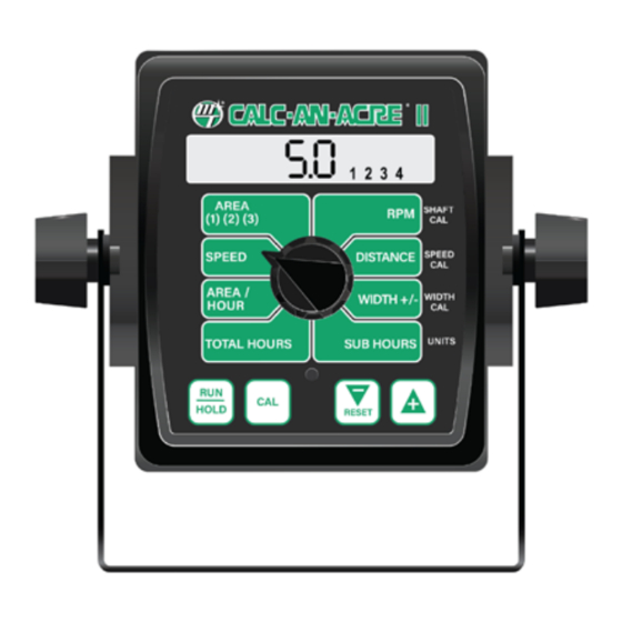
Calc-An-Acre II Console Func tions The Calc-An-Acre II features a large, easy-to-read liquid crystal display, easy-to-use rotary dial and lighted display. AREA (1) (2) (3): Three independent counters keep a RPM: Displays shaft RPM (requires Shaft Sensor Kit P/N running count of the total acres (hectares) (thousands of 01539) square feet) worked. -
Page 14: Calibration
Calibration English or Metric? The Calc-An-Acre II is capable of displaying in for ma tion in Amer i can En glish or standard Metric or Turf measurement units. The Calc-An- Acre II is shipped from the factory programmed for English. Note ®... -
Page 15: Entering Calibration Values
Calibration (cont) Entering Calibration Values SHAFT CAL: UNITS: This position is used to calibrate a shaft RPM Choose the system of units desired. Use the “+” sensor. A P/N 01539 Shaft RPM Sensor Kit is required. When and “-” buttons to choose between EnG this position is selected, (American English Units), mEt (Metric) and the display will show... - Page 16 Calibration (cont) Entering Calibration Values (cont) Determining the SPEED CAL (Skip this section if using radar or GPS speed sensor) For the console to calculate the correct speed and measure distance accurately, the circumference of the sensor-equipped wheel must be entered. Determine the circumference of the sensor-mounted wheel to the nearest tenth of an inch (tenth of a centimeter) with the fol low ing method:...
-
Page 17: Fine Tuning Speed/Distance Cal
Calibration (cont) Fine Tuning Speed/Distance Calibration Val ue PREPARATION When the display shows distance (“CAL” is flashing), ver i fy wheth er the number displayed is the ex act dis- In order to achieve accurate measurements, each step in tance you drove (with in + or - 1 - 2 %). If not, press the this fine tuning procedure should be performed as precisely “+”... -
Page 18: Operation
25%. The working width reverts back to the Width Cal the field. value when the Calc-An-Acre II power is turned off and back on. See the Calibration section page 15 for more In a full-width condition, the display will read “1 2 3 4”. To information. -
Page 19: Rotary Switch Positions
Operation To select an AREA counter: Verify that the desired counter is selected, or use the “+” button to select. Resetting System Counters Display indicates that counter #1 The AREA, DISTANCE, TOTAL HOURS and SUB HOURS is selected ® counters maintain a running count during operation regardless of the position of the rotary switch. -
Page 20: Troubleshooting
Troubleshooting Messages/Warnings This message appears when an error occurs while verifying calibration values during the power-up. Enter calibration and verify that the calibration values have not changed and exit calibration. Cycling power will not clear the bad CAL message. The message can only be cleared by entering and exiting calibration mode. -
Page 21: General
For easy-to-follow guidelines, refer to the If you have a two-way radio, it may be mounted too close troubleshooting section which follows. to the console. Keep all Calc-An-Acre II cables away from the radio, its antenna and power cable. CONSOLE APPEARS DEAD Ignition wires may be causing the console to malfunction. -
Page 22: Checking Individual Components
Troubleshooting (cont) Checking Individual Components CONSOLE MAGNETIC HALL-EFFECT SPEED SENSORS Caution: Improper connection or voltage could damage The only way to field test a console is to con nect it to a harness on a vehicle with a known working console or the Hall-effect sensor. -
Page 23: Checking Console Inputs
Troubleshooting (cont) Checking Console Inputs with Multimeter If there is no response from any of the following tests, refer to the main wiring diagram to locate the next connector in line to ward the con sole and repeat the test at that con- nec tor. -
Page 24: Appendices
Appendices... -
Page 25: Appendix A - Optional Speed Sensor Mounting Installation
Appendix A Speed Sensor and Bracket Optional Speed Sensor Mounting Installation Implement Wheels ¼” Bolts, Lockwashers 1. Secure magnets mechanically or with epoxy. and Nuts 2. Rigidly mount sensor mounting bracket to the wheel Speed Sensor assembly. Cut or bend “L” bracket as required for proper positioning of sensor. -
Page 26: Optional Speed Sensor Mounting Installation On Drive Shaft
• Secure sensor cable to frame with cable ties. Place first the shaft is turned. The magnets provided by Micro-Trak are tie as close to sensor assembly as possible. marked with a dashed line on the SOUTH pole side of the magnet. -
Page 27: Appendix B Radar "Y" Adapter Cables
Appendix B Radar “Y” Adapter Cables In-Cab Case MX Series Britax Connector Vansco Radar Amp Connector P/N 18319 P/N 14926 Signal Ground DICKEY-john Radar Amp Connector P/N 14812 In-Cab John Deere Metri-Pack Connector P/N 14810 8000/9000 Series 1. Ground 1. Ground 2. -
Page 28: Appendix C - Conversion Chart
Appendix C Conversion Chart English to Metric Metric to English When You Know Multiple By To Find When You Know Multiple By To Find LINEAR MEASUREMENT LINEAR MEASUREMENT inches 25.4 millimeters millimeters .039 inches feet 0.305 meters meters 3.28 feet yards 0.914 meters... -
Page 29: Appendix D - Replacement Parts
Appendix D Replacement Parts List The following replacement parts are available from your dealer or distributor. Micro-Trak Systems, Inc. 111 LeRay Ave. Eagle Lake, MN 56024-9650 When ordering parts, please list the model number of your console, and the description and part number of each part that you want to order. - Page 30 111 LeRay Ave. Eagle Lake, MN 56024-9650 Toll-Free: 800-328-9613 507-257-3600 • Fax 507-257-3001 www.micro-trak.com • trakmail@micro-trak.com Copyright © 2021 Micro-Trak Systems, Inc. All Rights Reserved. P/N 17192 • 082321...
Need help?
Do you have a question about the Calc-An-Acre II and is the answer not in the manual?
Questions and answers